heat sink

A radiator and heat sink technology, applied in indirect heat exchangers, heat exchanger shells, heat exchange equipment, etc., can solve problems such as application, obstruction of working fluid flow, weight increase, etc., to reduce thermal resistance and heat input. Effects of homogenization and excellent pressure resistance

Active Publication Date: 2022-04-29
FURUKAWA ELECTRIC CO LTD
View PDF7 Cites 0 Cited by
  • Summary
  • Abstract
  • Description
  • Claims
  • Application Information

AI Technical Summary

Problems solved by technology

However, if a solid columnar member or a block member is accommodated in the entire internal space of the container, although pressure resistance can be obtained, the weight of the solid columnar member or block member increases, so there is still thermal connection with the container. Stress from columnar parts or bulk parts is applied to electronic parts, etc.
In addition, columnar members and block members may hinder the circulation of the gaseous working fluid enclosed in the inner space of the container.

Method used


Image

  • heat sink
  • heat sink
  • heat sink

Examples


Embodiment Construction

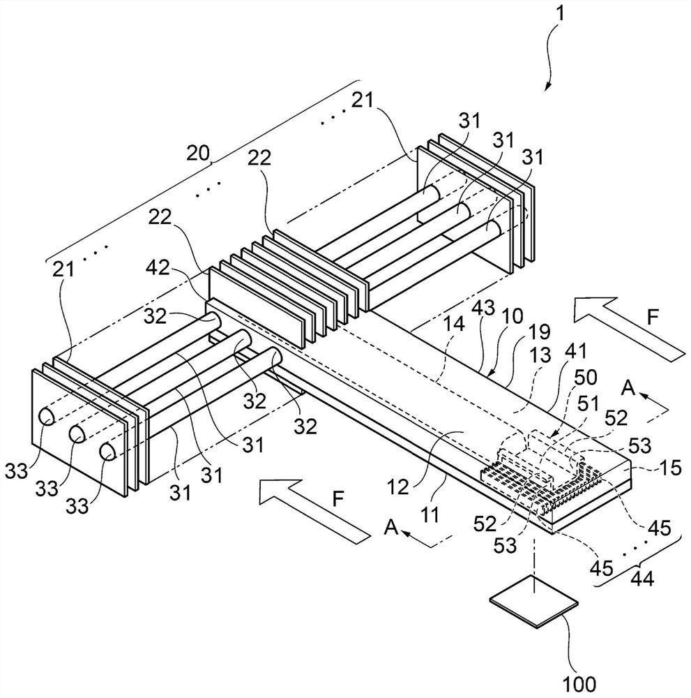
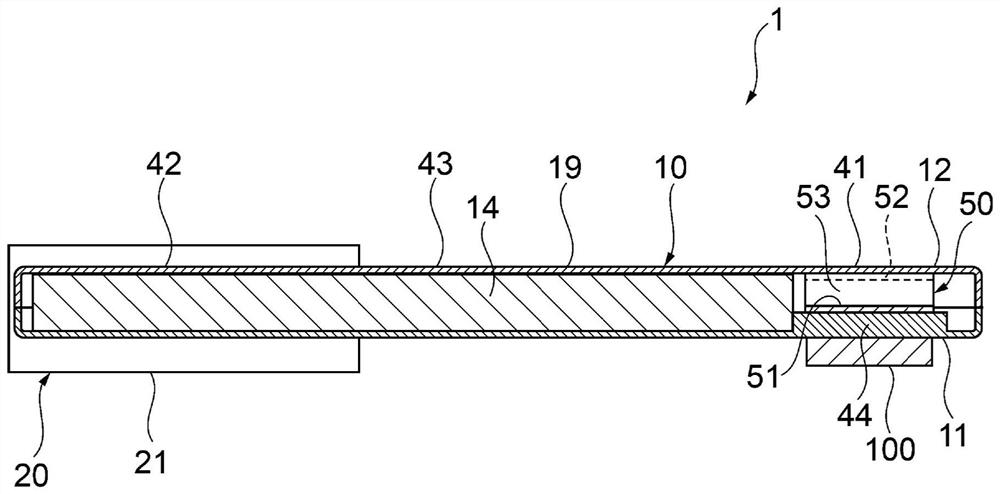
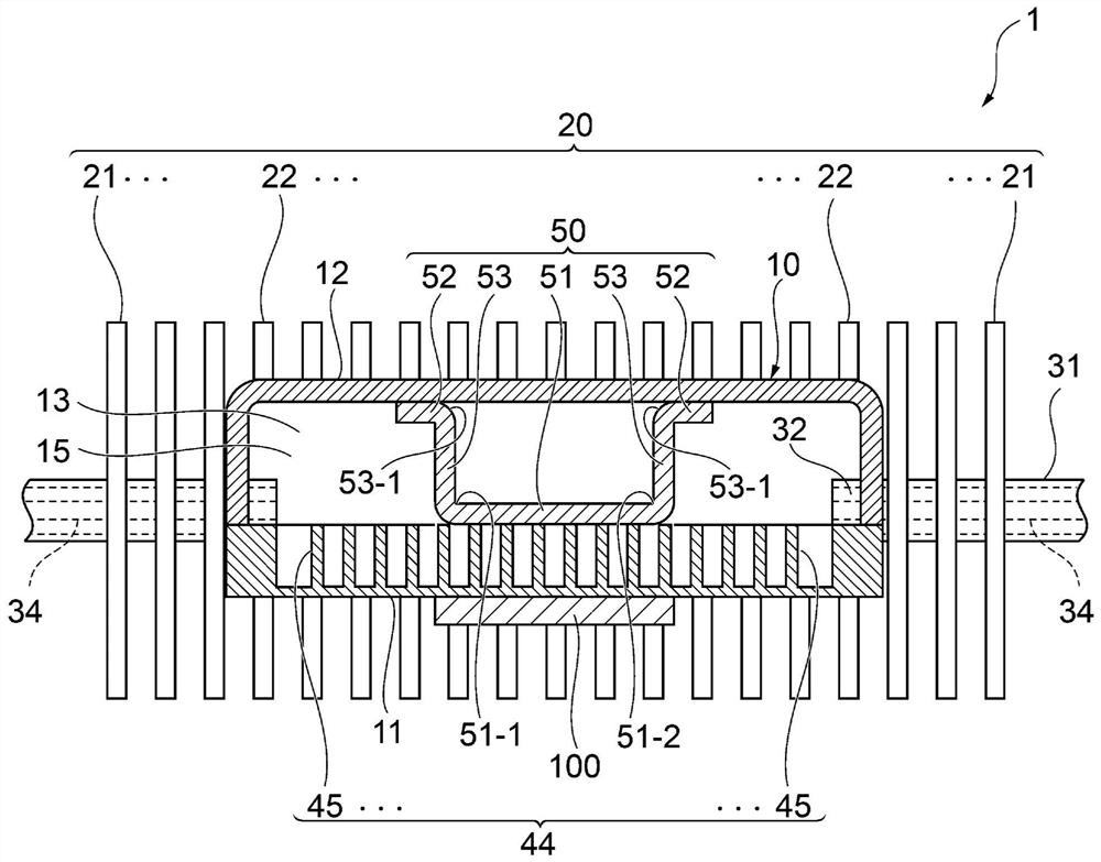
[0059] Hereinafter, a heat sink according to an embodiment of the present invention will be described with reference to the drawings. First, a heat sink according to a first embodiment of the present invention will be described. It should be noted, figure 1 It is a perspective view explaining the outline of the radiator of 1st Embodiment of this invention. figure 2 It is a side sectional view explaining the outline of the heat sink of 1st Embodiment of this invention. image 3 It is to explain the outline of the radiator of the first embodiment of the present invention figure 1 A-A cutaway view. Figure 4 It is an explanatory drawing which shows the outline|summary of the inside of the heat receiving part of the radiator of 1st Embodiment of this invention.

[0060] Such as figure 1 , figure 2 As shown, the radiator 1 of the first embodiment of the present invention has a heat transfer member 10 having a heat receiving portion 41 thermally connected to the heating elem...


PUM


Abstract

The present invention provides a radiator that includes a light-weight heat transfer member that has excellent pressure resistance to atmospheric pressure without impairing the flowability of a working fluid in the gaseous phase, and that can make the heat receiving portion of the heat transfer member Homogenization of heat input in. The heat sink includes: a heat transfer component having a heat receiving portion thermally connected to the heat generating body; The heat receiving part communicates with the heat dissipation part and is enclosed with an integral internal space of working fluid. In the internal space of the heat receiving part, an inner surface area increasing part of the heat receiving part and a support member are arranged, and the support member has an inner surface area of ​​the heat receiving part. Increase face-to-face contact.

Description

technical field [0001] The present invention relates to a heat sink for cooling electric / electronic components and the like, and more particularly to a heat sink provided with a light-weight heat transfer member having excellent pressure resistance. Background technique [0002] With the increase in performance of electronic equipment, heat generating elements such as electronic components are mounted on a substrate at a high density inside the electronic equipment. A heat sink may be used as means for cooling a heat generating body such as an electronic component. As the heat sink, generally, a heat sink (heat pipe type heat sink) including a plurality of tubular heat pipes functioning as heat transfer members is used. [0003] As a heat pipe type heat sink, for example, there is a heat pipe type heat sink in which a plurality of flat fins protrude from an outer peripheral surface provided with a plurality of tubular heat pipes (Patent Document 1). The heat sink disclosed...

Claims


Application Information

Patent Timeline
Patent Type & Authority Patents(China)
IPC IPC(8): H05K7/20F28D15/04F28F9/26
CPCH05K7/20336F28D15/043F28D15/046F28F9/262F28D15/04H01L23/427H01L23/36F28D15/0275F28D15/0266
Inventor 渡边阳介川畑贤也稻垣义胜三浦达朗青谷和明中村敏明
Owner FURUKAWA ELECTRIC CO LTD
Why Eureka
Try Eureka