Supercharge Your Innovation With Domain-Expert AI Agents!

Plug-plug holder device

A technology of plugs and switching elements, which is applied to parts of connection devices, devices to prevent wrong connections, coupling devices, etc., which can solve the problems of not being able to automatically check the correct positioning of the plug connection structure and expensive contact parts, etc.

Inactive Publication Date: 2020-11-06
BAYERISCHE MOTOREN WERKE AG
View PDF1 Cites 0 Cited by
  • Summary
  • Abstract
  • Description
  • Claims
  • Application Information

AI Technical Summary

Problems solved by technology

But such contacts are very expensive and cannot automatically check the correct positioning in the plug connection

Method used


Image

  • Plug-plug holder device
  • Plug-plug holder device
  • Plug-plug holder device

Examples


Embodiment Construction

[0027] In the following, elements that are the same or have the same function are denoted by the same reference numerals.

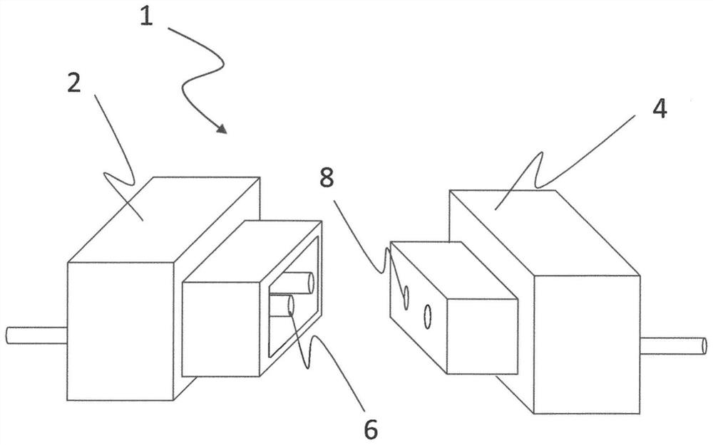
[0028] figure 1 A plug-plug-receptacle arrangement 1 with a plug 2 and a plug-receptacle 4 is shown. The plug 2 has, for example, a contact 6 which can be inserted into a corresponding receptacle 8 and into the plug receptacle 4 . If the contact 6 is connected to the receptacle 8 , current flows through the plug connection. However, if such a plug connection 1 is not plugged up to the stop, although electrical contact is formed between the contact 6 and the receptacle 8 , the tightness and vibration resistance of the connection will decrease over time. This can result in a complete release of the plug connection.

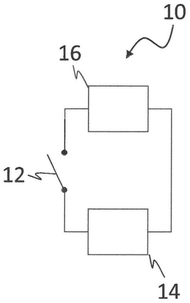
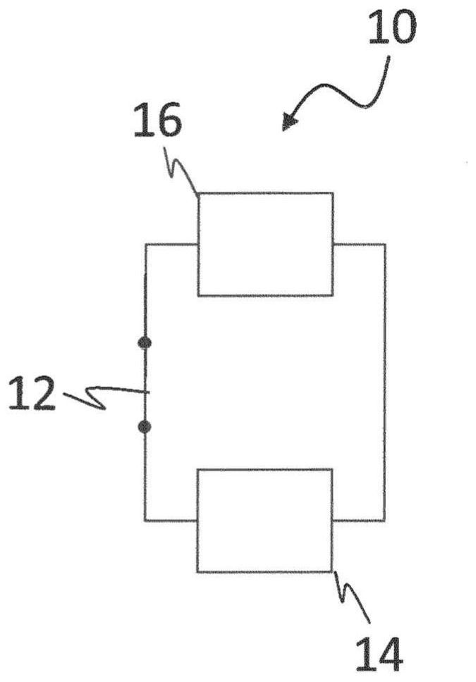
[0029] Therefore, in order to detect whether the plug 2 is correctly positioned in the plug receptacle 4 , that is to say positioned in the plug receptacle up to a stop, the identification unit 10 is used in the plug-plug receptacle arrangem...


PUM


Abstract

The invention relates to a plug-plug holder device comprising a plug, which can be inserted in a plug holder. The plug or the plug holder has a detection unit designed to detect the correct positioning of the plug in the plug holder, the detection unit having a switching element designed to be mechanically activated when the plug is correctly positioned.

Description

technical field [0001] The invention relates to a plug-plug-receptacle arrangement according to the preamble of claim 1 having a plug and a plug-receptacle into which the plug can be inserted. Background technique [0002] In critical areas, such as high-voltage systems, it is important to detect whether the plug connection, ie the connection between the plug and the plug-receptacle for the transmission of electrical energy, is correctly closed. Such plug connections are usually joined together manually. Depending on the design of the plug and plug receptacle or socket, ie the number of poles, the design of the contacts and the design of the housing, and other features, the required plugging force can vary considerably. If the plug-in connection is not plugged into the stop, the tightness and vibration resistance of such a plug-in connection will decrease over time, although electrical contact is usually still present. Ultimately this can lead to failure of the plug connec...

Claims


Application Information

Patent Timeline
Patent Type & Authority Applications(China)
IPC IPC(8): H01R13/641H01R13/66H01R13/703H01R13/03
CPCH01R13/641H01R13/6691H01R13/03H01R13/7031H01R13/7175
Inventor J·珀默尔
Owner BAYERISCHE MOTOREN WERKE AG
Features
  • R&D
  • Intellectual Property
  • Life Sciences
  • Materials
  • Tech Scout
  • Unparalleled Data Quality
  • Higher Quality Content
  • 60% Fewer Hallucinations
Learn More