Motor-vehicle door lock

A motor vehicle door lock and maneuvering technology, applied in the field of hatch locks or hood locks, to achieve the effect of effective clamping and protection

Active Publication Date: 2020-11-20
KIEKERT AG
View PDF9 Cites 0 Cited by
  • Summary
  • Abstract
  • Description
  • Claims
  • Application Information

AI Technical Summary

Problems solved by technology

Rather, the starting point of the known teaching is that once the pr...

Method used


Image

  • Motor-vehicle door lock
  • Motor-vehicle door lock

Examples


Embodiment Construction

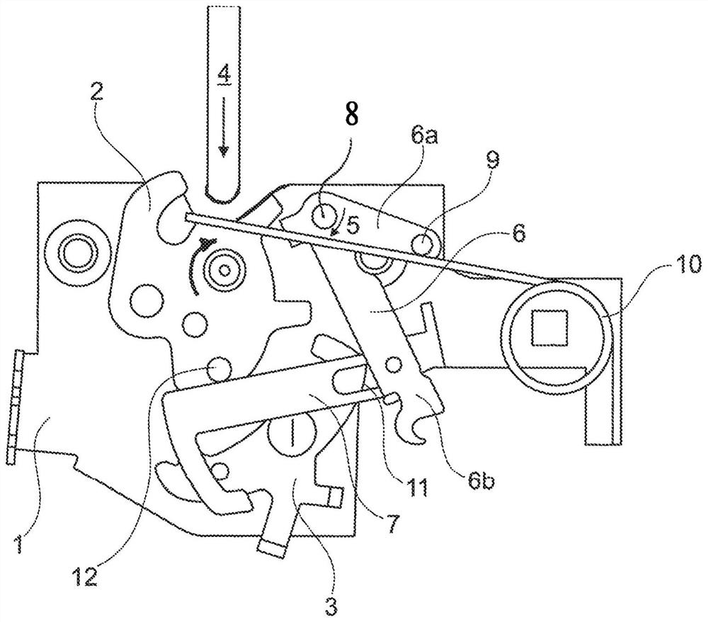
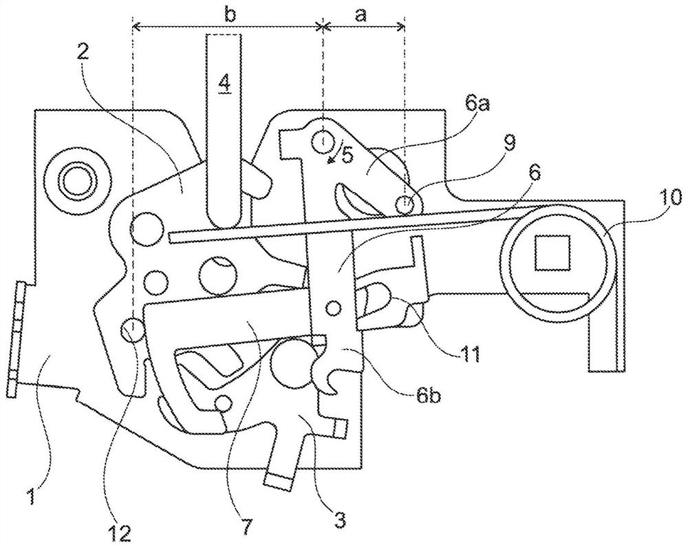
[0026] The drawing shows a motor vehicle door lock, which is not restricted to a hatch lock or a hood lock. In practice, the relevant motor vehicle door lock is used, for example, in combination with a front hood for covering the engine compartment in a motor vehicle. For this purpose, the motor vehicle door lock has a metallic lock box 1 in which a locking device 2 , 3 , which essentially consists of a rotary locking fork 2 and a pawl 3 , is rotatably mounted. Furthermore, a locking or locking pin 4 is provided, which is connected to a hood or hatch (not explicitly shown) or to the front hood already described above.

[0027] The motor vehicle door lock 1 shown in the example case is placed at the front of the motor vehicle body, for example in the region of a cooler arranged there or also in the region of the front hatch in vehicles with a rear engine. middle. In order to close the front hatch, the associated hood or hatch is lowered.

[0028] Corresponding to this is the...


PUM


Abstract

The subject matter of the present invention is a motor-vehicle door lock, more particularly a flap lock or a hood lock. The basic design of the motor-vehicle door lock is equipped with a locking mechanism (2, 3) substantially consisting of a rotary latch (2) and a pawl (3). There is also a motorized closing aid (5, 6, 7) which has a motor (5) and also a first lever (6), which is acted upon by themotor (5), and a second lever (7). The two levers (6, 7) are hinged to each other. According to the invention, during the lowering of a flap or hood, the second lever (7) first of all carries out a movement, which is controlled by the rotary latch (2), while simultaneously freewheeling in relation to the first lever (6). Only following the freewheeling does the first lever (6), which is then driven, act upon the second lever (7), in order to close the rotary latch (2).

Description

technical field [0001] The invention relates to a motor vehicle door lock, in particular a hatch lock or hood lock, having a locking device mainly comprising a rotary lock fork and a locking pawl, and a motorized automatic closing device with a motor And a first lever and a second lever loaded by a motor, wherein the two levers are rotatably hinged to each other. Background technique [0002] Hatch or hood locks are commonly used in conjunction with hatches or hoods on motor vehicles to lock the associated hatch or hood relative to the body of the motor vehicle. The relevant cover can be a front cover for covering the engine compartment, or a rear hatch, a side hatch, etc. Of course, these hatch locks or hood locks must overcome relatively large play during closing. Therefore, such motor vehicle door locks are usually equipped with catch hooks for additional fastening. [0003] In order to be able to close the above-mentioned large gap regions, relatively complex kinemati...

Claims


Application Information

Patent Timeline
IPC IPC(8): E05B81/20E05B83/24E05B81/06
CPCE05B15/004E05B81/06E05B81/21E05B83/24
Inventor B·德罗斯特M·厄兹多安M·舒尔茨H·施弗尔
Owner KIEKERT AG
Why Eureka
Try Eureka