An active cooling engine fuel switching device and switching method

An active cooling and switching device technology, applied in the direction of engine components, engine cooling, turbine/propulsion device cooling, etc., can solve the problems of reduced penetration depth, engine flameout, descent, etc.

Active Publication Date: 2021-07-09
合肥中科重明科技有限公司 +1
View PDF7 Cites 0 Cited by
  • Summary
  • Abstract
  • Description
  • Claims
  • Application Information

AI Technical Summary

Problems solved by technology

[0007] However, due to the instantaneous increase of the injection area when switching, there is a certain lag in the establishment of the injection pressure, resulting in a decrease in the penetration depth, an instantaneous drop in the total pressure and thrust of the combustion chamber, resulting in a decrease in engine combustion efficiency, and may even cause the engine to stall during the switchover process.

Method used


Image

  • An active cooling engine fuel switching device and switching method
  • An active cooling engine fuel switching device and switching method
  • An active cooling engine fuel switching device and switching method

Examples


Embodiment 1

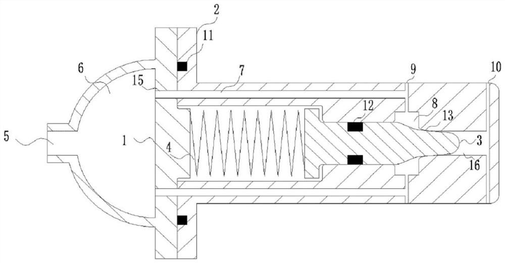
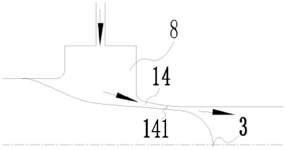
[0040] An active cooling engine fuel switching device, comprising a housing 2 with one end open, and an end flange 1 is installed on the opening side of the housing 2, and the side of the inner cavity of the housing 2 away from the end flange 1 is sequentially provided with Through the confluence chamber 8 and the downstream chamber 16, the needle cone 3 is inserted in the inner cavity of the housing 2, and the head of the needle cone 3 penetrates the confluence chamber 8 and extends to the downstream chamber 16, the confluence chamber 8 and the downstream chamber The junction of the chamber 16 is provided with an inner flow channel wall 13 matching the side wall of the needle cone 3, and a contraction-expansion flow channel 14 is formed between the side wall of the needle cone 3 and the inner flow channel wall 13, and the contraction-expansion flow The section of the channel 14 close to the confluence cavity 8 is a contraction section, and the section close to the downstream c...

Embodiment 2

[0057] This embodiment provides a fuel switching method based on an active cooling engine fuel switching device, including the following steps:

[0058] S1. The fuel flows through the fuel inlet 5, the buffer chamber 6, the inner flow channel 15 of the end flange and the inner flow channel 7 of the housing to the confluence cavity 8 and the upstream injection hole 9;

[0059] S2. According to the different states of the fuel, the fuel switching device performs self-adaptive adjustment;

[0060] S2-1. When the fuel is in liquid state, the resultant force of the fuel pressure in the manifold chamber 8 and the gas pressure in the downstream chamber 16 on the surface of the needle cone 3 is less than the preload force of the elastic element 4, and the needle cone 3 is under the preload force of the elastic element 4. Fit the inner runner wall 13 under tight force, and the fuel is injected from the upstream nozzle hole 9;

[0061] S2-2. When the fuel is in a supercritical or gaseo...


PUM


Abstract

The invention relates to the field of engine fuel injection, and provides an active cooling engine fuel switching device, so that when the fuel enters a supercritical state or a gas state from a liquid state, the cross-sectional area of ​​the fuel injection hole is adaptively adjusted according to the fuel pressure change, and the fuel injection pressure is kept stable. In order to ensure stable combustion of the engine during the fuel switching process, it includes a shell with one end open, and an end flange is installed on the open side of the shell, and the side of the shell inner cavity facing away from the end flange is sequentially provided with a confluence cavity and a downstream cavity The needle cone is inserted into the inner cavity of the housing, and the head of the needle cone penetrates the confluence cavity and extends to the downstream chamber. The connection between the confluence cavity and the downstream chamber is provided with a Inner channel wall. The invention also provides an active cooling engine fuel switching method. The invention is especially suitable for fuel stable switching of active cooling engines, and has high social use value and application prospect.

Description

technical field [0001] The invention relates to the field of engine fuel injection, in particular to an active cooling engine fuel switching device and a switching method. Background technique [0002] Actively cooled engines require fuel to cool and protect the walls of the engine's combustion chamber before being injected into the combustion chamber for combustion. The advantages of active cooling technology are reflected in the following aspects: [0003] 1) Cool the combustion chamber, protect the combustion chamber from combustion damage, and prolong the working life of the combustion chamber; [0004] 2) It can preheat fuel, improve combustion efficiency, and obtain greater thrust; [0005] 3) A cooling channel is provided inside the combustion chamber to reduce the weight of the combustion chamber. [0006] As the total temperature of the combustion chamber increases, the temperature of the fuel flowing out of the cooling channel of the combustion chamber also incr...

Claims


Application Information

Patent Timeline
Patent Type & Authority Patents(China)
IPC IPC(8): F02C9/26F02C9/32F02C7/12
CPCF02C7/12F02C9/26F02C9/32
Inventor 袁越明吴坤赵林英范学军
Owner 合肥中科重明科技有限公司
Why Eureka
Try Eureka