Connecting mechanism convenient to assemble

A connecting mechanism and rotating connection technology, which is applied in the direction of connecting components, mechanical equipment, etc., can solve the problems of heavy workload, easy slippage of bolts, and easy existing problems, so as to ensure smoothness, avoid screw failure, and prevent buckle components from being lost Effect

Inactive Publication Date: 2020-11-24
周玉琴
View PDF13 Cites 0 Cited by
  • Summary
  • Abstract
  • Description
  • Claims
  • Application Information

AI Technical Summary

Problems solved by technology

[0002] In the mechanical field, the connection between components is basically assembled and fixed by bolts. Although it can be fixed, in some special cases, such as the three-dimensional rotating platform, which belongs to the precision servo instrument, in the daily use process, its Accuracy is often prone to problems. At this time, it is necessary to disassemble and test the parts of the turntable. During this process, it is necessary to continue to rotate in order to remove all the bolts used for assembly and fixing. The workload is heavy and very troublesome. After dismantling, multiple Bolts can easily lead to the loss of individual bolts during the tension test of each component, which affects the normal assembly and use of the 3D turntable. At the same time, the bolts are also very easy to slip during frequent disassembly and assembly tests.

Method used


Image

  • Connecting mechanism convenient to assemble
  • Connecting mechanism convenient to assemble
  • Connecting mechanism convenient to assemble

Examples


Embodiment Construction

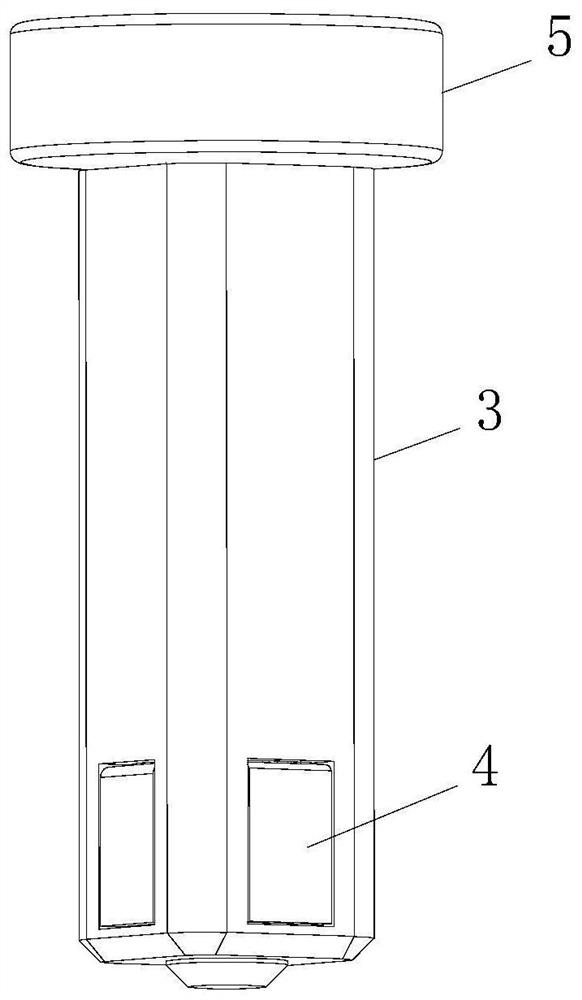
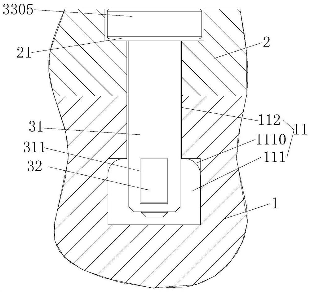
[0037] Such as Figure 1-Figure 8 As shown, a connection mechanism for easy assembly, including the first part 1 and the second part 2 to be connected;

[0038] The first part 1 includes a first groove 11, the first groove 11 is narrow on the outside and wide on the inside; the second part 2 is provided with a buckle assembly that can go deep into the first groove 11;

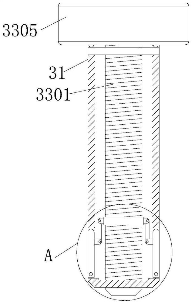
[0039] The buckle assembly includes a sleeve 31 and a force applying unit 33. At least one functional hole 311 is opened on the side wall of the sleeve 31, and each functional hole 311 is provided with a deflection buckle 32. The deflection buckle The lower end of the plate 32 is hinged with the sleeve 31, and the force applying unit 33 drives the upper end of the deflection pinch plate 32 to be replaced between two stations. The first station is located in the functional hole 311, and the second station is located in the sleeve. The outside of the cylinder 31 can make the buckle part be locked in the first gr...


PUM


Abstract

A connecting mechanism convenient to assemble comprises a first component and a second component which need to be connected. The first component comprises a first groove, the outer part of the first groove is narrow, and the inner part of the first groove is wide; and the second component is provided with a buckle assembly which can extend into the first groove. The buckle assembly comprises a sleeve and a force application unit. At least one functional hole is formed in the side wall of the sleeve. A deflection clamping plate is arranged in each functional hole. The lower ends of the deflection clamping plates are hinged to the sleeve. The force application unit drives the upper end of each deflection clamping plate to be switched between two stations. The first stations are located in the functional holes. The second station is located outside the sleeve and makes a buckle part clamped in the first groove. The buckle assembly is disposed on the second component so that the buckle assembly is prevented from being lost. When a product is stressed in the axial direction of a screw, force is borne through screw threads. The deflection clamping plates are located in the second stationto abut against the first groove. In this way, the situation that a lot of screws fail due to screw thread slippage is avoided.

Description

technical field [0001] The invention relates to the field of mechanical technology, in particular to a connection mechanism for easy assembly. Background technique [0002] In the mechanical field, the connection between components is basically assembled and fixed by bolts. Although it can be fixed, in some special cases, such as the three-dimensional rotating platform, which belongs to the precision servo instrument, in the daily use process, its Accuracy is often prone to problems. At this time, it is necessary to disassemble and test the parts of the turntable. During this process, it is necessary to continue to rotate in order to remove all the bolts used for assembly and fixing. The workload is heavy and very troublesome. After dismantling, multiple Bolts can easily lead to the loss of individual bolts during the tension test of each component, which affects the normal assembly and use of the 3D turntable. At the same time, the bolts are also very easy to slip during fr...

Claims


Application Information

Patent Timeline
IPC IPC(8): F16B21/16
CPCF16B21/16
Inventor 周玉琴
Owner 周玉琴
Why Eureka
Try Eureka