
Rotary handle device

A technology of rotating handles and handles, which is applied in the field of photographic equipment, can solve problems such as falling of photographic equipment and inconvenient operation, and achieve the effect of ensuring safety

Active Publication Date: 2020-11-24
SHENZHEN LEQI NETWORK TECH CO LTD
View PDF6 Cites 5 Cited by
  • Summary
  • Abstract
  • Description
  • Claims
  • Application Information

AI Technical Summary

Problems solved by technology

However, the button of the above-mentioned handle device is at the end of the handle. When triggering, it is necessary to move the grip position or put down the bracket to press the button. This is not only inconvenient to operate, but also may cause the photographic equipment to fall.

Method used


Image

  • Rotary handle device
  • Rotary handle device
  • Rotary handle device

Examples


Embodiment Construction

[0038] In order to facilitate the understanding of the present invention, the present invention will be described more fully below with reference to the associated drawings. One or more embodiments of the present invention are exemplarily shown in the drawings, so as to make the understanding of the technical solutions disclosed in the present invention more accurate and thorough. However, it should be understood that the present invention can be implemented in various forms and is not limited to the embodiments described below.

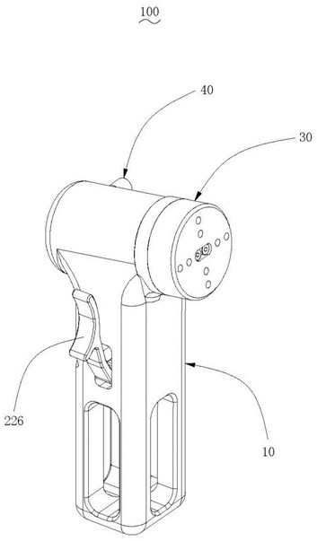
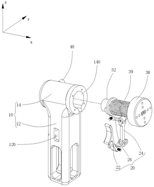
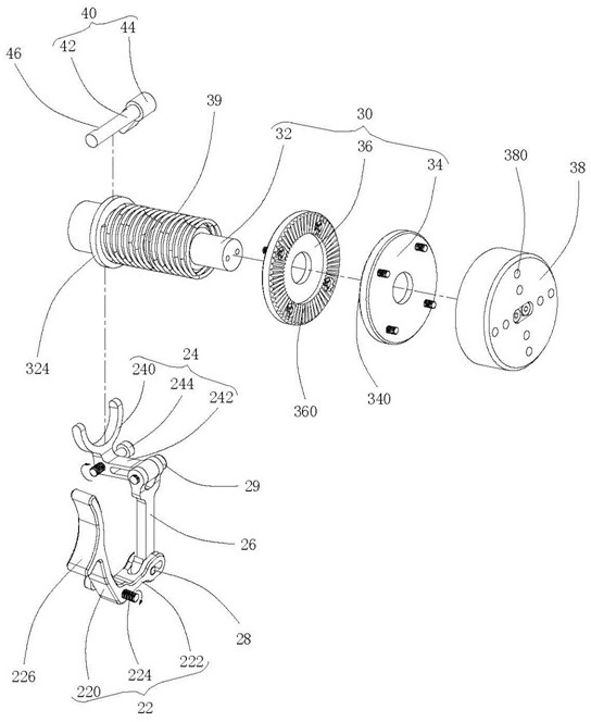
[0039] Such as Figure 1-3 As shown, a rotating handle device 100 according to an embodiment of the present invention includes a handle 10 , a driving mechanism 20 installed in the handle 10 , and a locking mechanism 30 driven by the driving mechanism 20 . The rotary handle device 100 shown is used to be installed on a bracket, and the bracket can be used to install related photographic accessories such as cameras and video cameras. For example, the...


PUM


Abstract

A rotary handle device comprises a handle, a locking mechanism and a driving mechanism. The locking mechanism comprises a rotary locking piece fixedly connected with the handle, the rotary locking piece can rotate around a pivot axis at an unlocked position, and the rotary locking piece is prevented from rotating around the pivot axis at a locked position. The driving mechanism is used for drivingthe locking mechanism, so the rotary locking piece converts on the locking position and the unlocking position. The driving mechanism comprises an operating part used for starting. The operating partis pressed to rotate around a first shaft rod so as to start the driving mechanism, the rotary locking part is unlocked from the locking position to the unlocking position, and therefore the handle is allowed to rotate around the pivot axis. According to the rotating handle device, the operating piece is hooked by fingers to rotate the handle, unlocking operation is conducted under the conditionthat the holding position of the handle is not changed, photographic equipment is effectively prevented from falling off, and photographic safety is guaranteed.

Description

technical field [0001] The invention relates to the technical field of photographic equipment, in particular to a rotary handle device. Background technique [0002] With the improvement of living standards, more and more people fall in love with photography. However, photographic equipment is bulky and heavy, and most of them are mounted on the shoulders of the human body through a shoulder-mounted bracket when in use, so as to reduce the load on the user's hands and allow the user to take pictures for a long time. The shoulder bracket usually includes a handle for holding. For example, Chinese Patent Publication No. CN102971116A discloses an adjustable handle device with a locking mechanism. By pressing the button, the rotation locking part is locked or unlocked. When the rotation locking part is unlocked Allowing the handle to pivot about the pivot axis adjusts the position of the handle. However, the button of the above-mentioned handle device is at the end of the hand...

Claims


Application Information

Patent Timeline
Patent Type & Authority Applications(China)
IPC IPC(8): G03B17/56
CPCG03B17/56G03B17/563
Inventor 林强
Owner SHENZHEN LEQI NETWORK TECH CO LTD
Learn More