
Method and device for testing shell attack angle and target position based on double vertical targets

A test method and dual target technology, applied to targets, offensive equipment, target indication systems, etc., can solve problems such as non-reusability, inability to distinguish whether the shells overlap the target or miss the target, and it is difficult to obtain the precise position of the shells, and achieves real-time performance. Good results

Inactive Publication Date: 2013-09-25
BEIJING INSTITUTE OF TECHNOLOGYGY
View PDF0 Cites 7 Cited by
  • Summary
  • Abstract
  • Description
  • Claims
  • Application Information

AI Technical Summary

Problems solved by technology

[0005] (1) Whether the shells overlap the target or miss the target cannot be distinguished
Since the existing real target test method calculates various technical indicators by manually reading the position of the bullet holes on the target surface after the live ammunition is fired, it is impossible to distinguish whether the overlapping shells pass the target or miss the target, and once a mistake is made, it will bring great testing error
[0006] (2) The real-time performance of the test process is poor
And all target reading work must be done manually, which is very dangerous
[0007] (3) The target surface is disposable and cannot be reused
Due to the extremely fast speed of the shell, the imaging quality is not high, and it is difficult to obtain the precise position of the shell
[0012] (4) The existing test device cannot test the instantaneous velocity of the projectile

Method used


Image

  • Method and device for testing shell attack angle and target position based on double vertical targets
  • Method and device for testing shell attack angle and target position based on double vertical targets
  • Method and device for testing shell attack angle and target position based on double vertical targets

Examples


Embodiment Construction

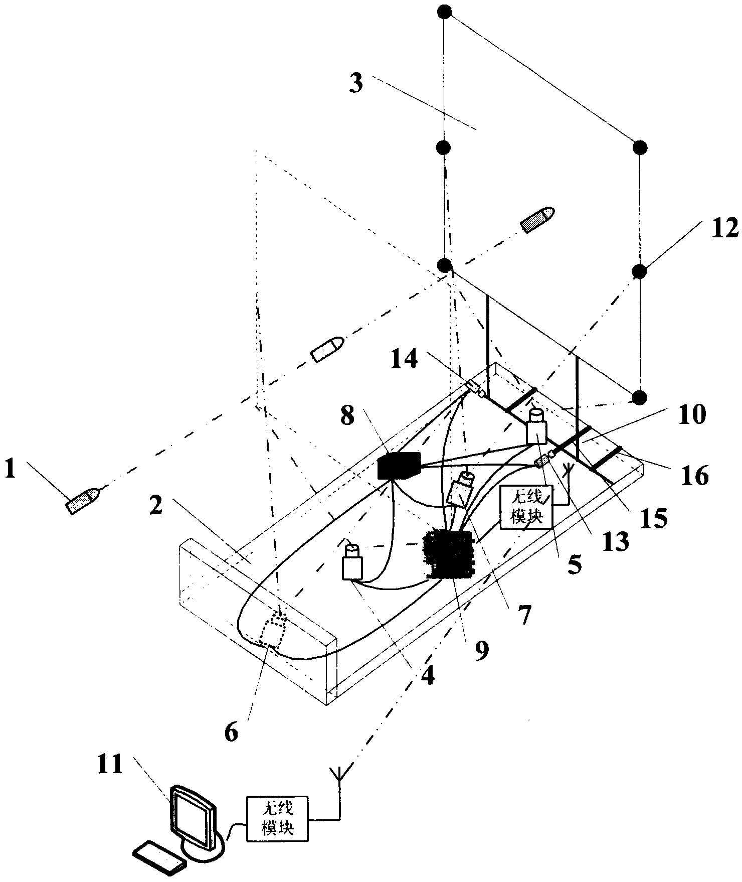
[0052] In order to better illustrate the purpose and advantages of the present invention, it will be further described below in conjunction with the accompanying drawings and live ammunition shooting test examples of artillery.

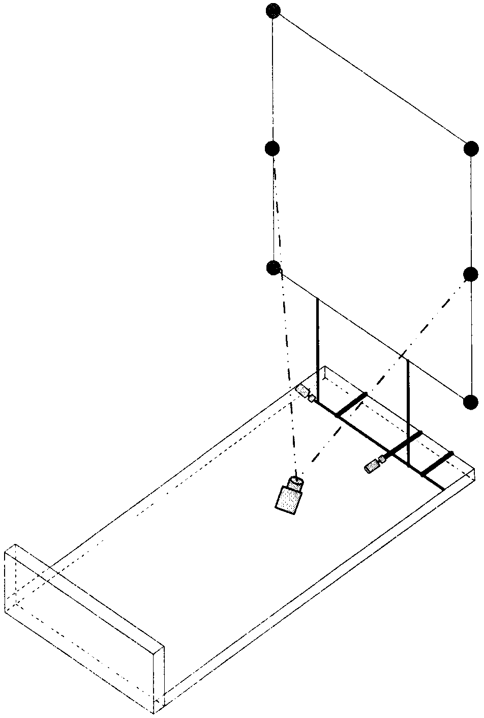
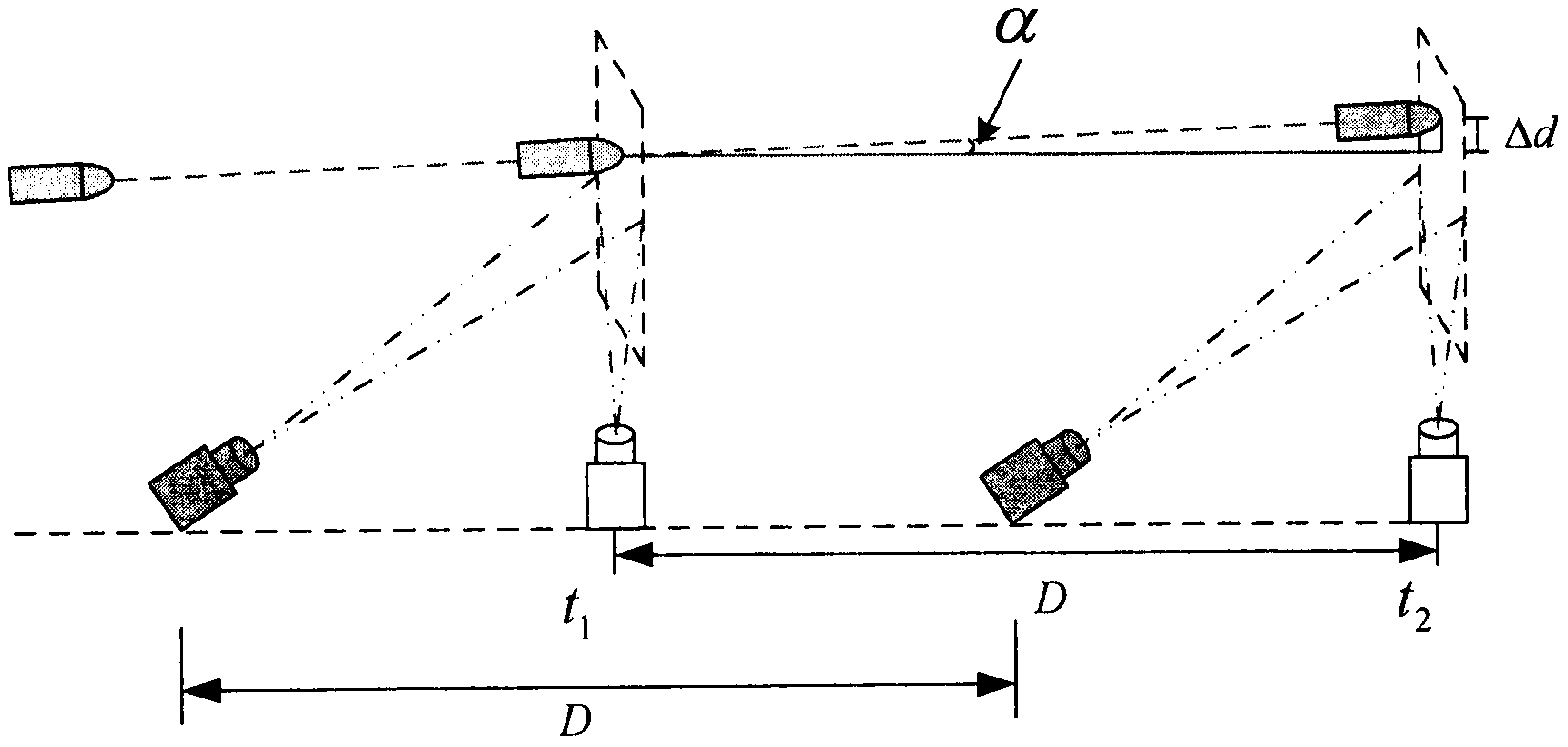
[0053] The method for testing the angle of attack and the position of the target of the projectile based on the dual vertical target of the present invention is as follows: two high-speed line array cameras and two area array cameras placed on a straight line are used to form a dual vertical target. Calibrate the calibration target surface to obtain the calibration point data and real-time detection of the image of the shell passing through. At the same time, the embedded image processing system processes the image collected by the high-speed line array camera and records the time when the shell passes through the two high-speed line array cameras. Once monitored When the shell passes through the high-speed line array camera, it immediately sends a tri...


PUM


Abstract

The invention relates to a method and device for testing the attack angle and target position of a shell based on double vertical targets, and belongs to the field of artillery test and test. The present invention consists of two area array cameras and two high-speed line array cameras to form a double-standing virtual target surface. The image processing system processes the images collected by the two high-speed line array cameras and records the time when the shell passes through the two high-speed line array cameras. Once it detects that the shell passes through the high-speed line array camera, it immediately sends a trigger signal to the corresponding area array camera for collection. The image when the shell passes through the virtual target surface; it is transmitted to the embedded system for processing and calculation to obtain performance indicators such as the angle of attack of the shell and relative shooting accuracy. The invention can simultaneously test the vertical and horizontal attack angles, the target position and the relative shooting accuracy of the shell at a certain distance, and can provide reference for the shooting accuracy of the actual impact point.

Description

technical field [0001] The invention relates to a method and device for testing the attack angle and target position of a shell based on double vertical targets, and belongs to the field of artillery test and test. Background technique [0002] The flight attitude and target position of shells are the main test items in various weapon range tests. The angle of attack refers to the angle between the axis of the projectile in flight and the movement direction of its center of mass. Since the projectile is in a state of adjustment during the initial flight, the attack angle of the projectile changes accordingly, and the change of the attack angle is directly related to the flight stability of the projectile. Therefore, the angle of attack of the shell is an important parameter to describe the flight attitude of the shell. In addition, the target position of the shell is also an important indicator to measure the shooting accuracy of the shell. Testing the shell's angle of att...

Claims


Application Information

Patent Timeline
Patent Type & Authority Patents(China)
IPC IPC(8): F41J5/10F41J5/00
Inventor 李静王军政汪首坤沈伟
Owner BEIJING INSTITUTE OF TECHNOLOGYGY
Learn More