Braking force distribution method, device and system for urban rail train
A technology of braking force distribution and braking system, applied in the field of braking force distribution of urban rail trains, can solve problems such as prolonged braking distance, reduced braking force, scratches on wheel treads, etc., and achieve the effect of reducing the probability of skidding
- Summary
- Abstract
- Description
- Claims
- Application Information
AI Technical Summary
Problems solved by technology
Method used
Image

Examples
Embodiment 1
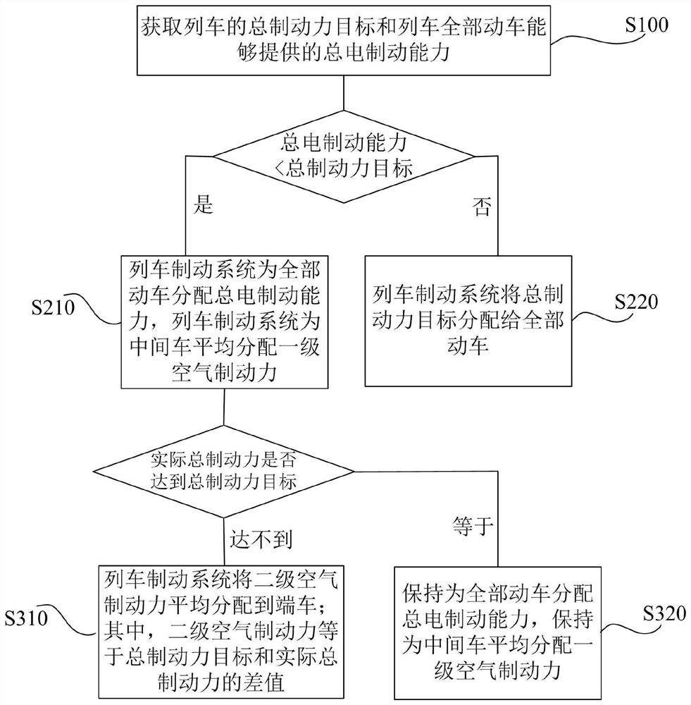
[0027] figure 1 It is a flow chart of braking force distribution of a braking force distribution method for urban rail trains according to an embodiment of the present application. Such as figure 1 As shown, a method for distributing braking force of an urban rail train in the embodiment of the present application includes the following steps:
[0028] Step S100: Obtain the total braking force target of the train and the total electric braking capacity that all motor cars of the train can provide; wherein, the total braking force target is calculated by the train braking system, and the total electric braking capacity is calculated by the train traction system Calculate;
[0029] The train traction system feeds back the total electric braking capacity to the train braking system through the train network system;
[0030] The train braking system compares the total electric braking capacity and the total braking force target. After the comparison, two situations will appear:...
Embodiment 2
[0050] The braking force distribution method for urban rail trains in the embodiment of the present application is a braking force distribution method based on the first embodiment of the present application.
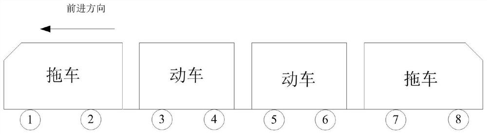
[0051] The embodiment of the present application is a braking force distribution method in the case that the leading car and the trailing car of the urban rail train are trailers.
[0052] During the implementation, when the leading car and the trailing car are trailers, the braking force allocation method is implemented until the total electric braking capacity is less than the total braking force target, the total electric braking capacity is allocated to all the motor vehicles, and an average distribution is made to the middle vehicle. During this step of level air braking force, the actual braking force of the train is provided by the middle car, and the leading car and the trailing car do not provide the actual braking force.
[0053] When the actual total braking ...
Embodiment 3
[0077]The braking force distribution method for urban rail trains in the embodiment of the present application is a braking force distribution method based on the first embodiment of the present application.
[0078] The embodiment of the present application is the braking force distribution method when the head car and the trailing car of the urban rail train are bullet trains. Car, tail car and middle car are offered together.
[0079] The braking force distribution method for urban rail trains in the embodiment of the present application is a braking force distribution method based on the first embodiment of the present application.
[0080] In the embodiment of the present application, when the head car and the tail car of the urban rail train are motor cars, the braking force distribution method allocates the total electric braking capacity for all motor cars when the total electric braking capacity is less than the total braking force target, which is the middle After t...
PUM
 Abstract
Description
Claims
Application Information
 - R&D Engineer
- R&D Manager
- IP Professional
- Industry Leading Data Capabilities
- Powerful AI technology
- Patent DNA Extraction
Browse by: Latest US Patents, China's latest patents, Technical Efficacy Thesaurus, Application Domain, Technology Topic.
© 2024 PatSnap. All rights reserved.Legal|Privacy policy|Modern Slavery Act Transparency Statement|Sitemap