Supercharge Your Innovation With Domain-Expert AI Agents!

A turbine hydrodynamic cavitation generator

A hydraulic cavitation and generator technology, applied in chemical instruments and methods, water/sewage treatment, water/sewage treatment equipment, etc., can solve unsatisfactory cavitation efficiency, low frequency of cavitation shedding and collapse, and reduce cavitation Efficiency and other issues, to achieve the effect of strengthening the performance of organic sewage treatment, increasing the frequency of cavitation shedding and collapsing, and increasing the cavitation degradation area

Active Publication Date: 2022-06-21
JIANGSU UNIV
View PDF15 Cites 0 Cited by
  • Summary
  • Abstract
  • Description
  • Claims
  • Application Information

AI Technical Summary

Problems solved by technology

Existing traditional cavitation generators include orifice plates, venturi tubes, etc. They have simple structures and low manufacturing and operating costs, but they also have shortcomings such as small cavitation areas, low cavitation intensity, and low frequency of cavitation shedding and collapse. Disadvantages lead to insufficient cavitation reaction and unsatisfactory cavitation efficiency
However, many emerging rotating cavitation generators also have problems such as complex structures and high production and operation costs.
In addition, the rotating cavitation generator needs to be driven by a high-speed motor, which increases energy consumption and reduces cavitation efficiency

Method used


Image

  • A turbine hydrodynamic cavitation generator
  • A turbine hydrodynamic cavitation generator
  • A turbine hydrodynamic cavitation generator

Examples


Embodiment Construction

[0026] The present invention will be further described below with reference to the accompanying drawings and specific embodiments, but the protection scope of the present invention is not limited thereto.

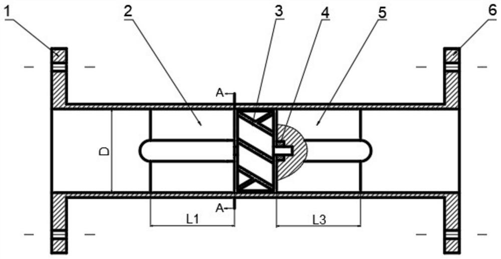
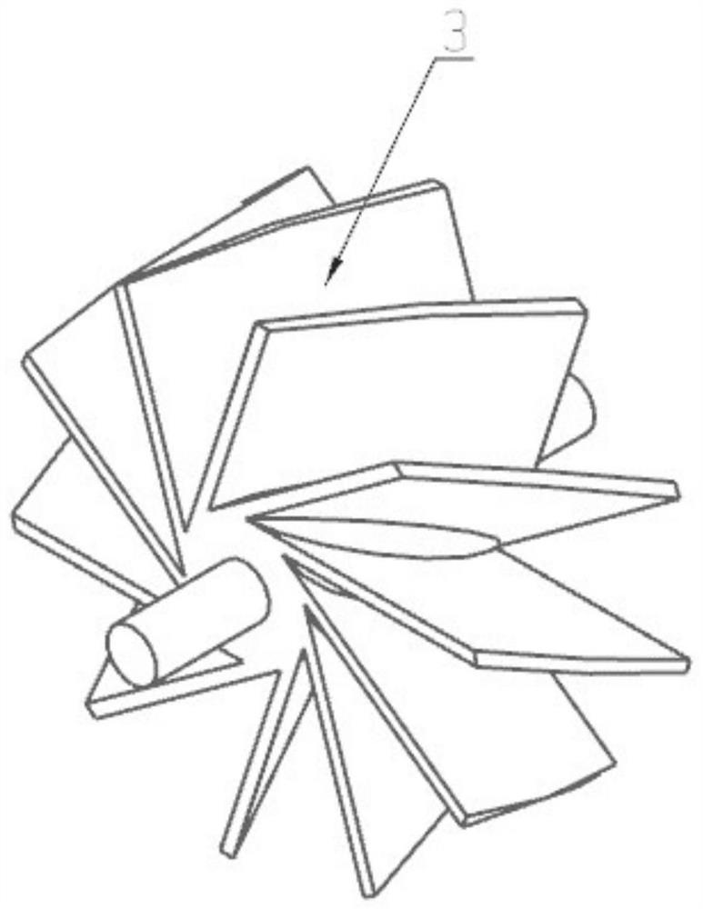
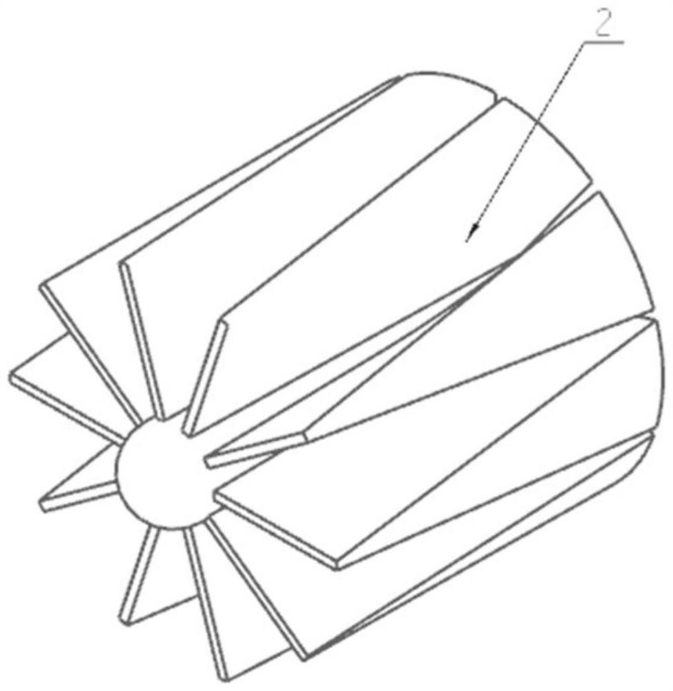
[0027] like figure 1 and Figure 4 As shown, the turbine hydraulic cavitation generator of the present invention includes several stages of cavitation units connected in series with each other, the cavitation units of each stage are connected by flanges, and the cavitation units of each stage include a shell, a left The stationary blade cascade 2, the right stationary blade cascade 5 and the turbine rotor 3; the left stationary blade cascade 2 and the right stationary blade cascade 5 are symmetrical structures, the left stationary blade cascade 2 is installed near the shell inlet flange 1, the right stationary blade cascade 5 Installed close to the shell outlet flange 6, between the symmetrically installed left stator blade cascade 2 and the right stator blade cascade 5, a...


PUM

PropertyMeasurementUnit
angleaaaaaaaaaa
thicknessaaaaaaaaaa

Abstract

The invention provides a turbine hydrodynamic cavitation generator, which comprises several stages of cavitation units connected in series, and each stage of the cavitation unit includes a casing, a stationary vane cascade and a turbine rotor; two Symmetrical static blade cascades, and one static blade cascade is close to the casing inlet, and the other static blade cascade is close to the casing outlet; a rotatable turbine rotor is installed between the two symmetrical static blade cascades, and the two ends of the turbine rotor They are respectively supported in two symmetrical stationary cascades; the thickness of the vanes of the stationary cascade near the inlet of the casing gradually increases along the flow direction, and the cross-sectional area of ​​flow between adjacent vanes remains constant in the radial direction; close to The thickness of the blades of the stationary cascade at the outlet of the casing decreases gradually along the flow direction, and the cross-sectional area of ​​flow between adjacent blades remains constant along the radial direction. The present invention utilizes static-dynamic-static arrangement to realize two-stage cavitation, effectively increasing the cavitation area.

Description

technical field [0001] The invention relates to the field of sewage treatment, in particular to a turbine hydraulic cavitation generator. Background technique [0002] With the continuous development of industry and agriculture and the great improvement of people's living standards, the problem of water pollution has become increasingly prominent, seriously restricting the sustainable development of the economy, and posing a threat to the health of human drinking water and the living environment of organisms. Sewage treatment is imminent and has become a problem that must be faced and solved together. Traditional sewage treatment methods include physical sedimentation method, biological absorption decomposition method, chemical reaction method, etc. However, they all have corresponding drawbacks. For example, the physical sedimentation method generally has high treatment cost, long action time, and insignificant effect; the biological method may destroy the local biological...

Claims


Application Information

Patent Timeline
Patent Type & Authority Patents(China)
IPC IPC(8): C02F1/34
CPCC02F1/34C02F2201/007
Inventor 王勇张国翔刘厚林张可可董亮谈明高王凯
Owner JIANGSU UNIV
Features
  • R&D
  • Intellectual Property
  • Life Sciences
  • Materials
  • Tech Scout
  • Unparalleled Data Quality
  • Higher Quality Content
  • 60% Fewer Hallucinations
Learn More