A rainwater drainage system riser embedded floor drain

A drainage system and riser technology, applied in waterway systems, water supply devices, roof drainage, etc., can solve problems such as water leakage, cracks in sealing materials, etc., and achieve the effects of enhancing drainage capacity, avoiding flattening, and enhancing the siphon effect

Active Publication Date: 2022-04-08
LINHAI WEIXING NEW BUILDING MATERIALS CO LTD
View PDF0 Cites 0 Cited by
  • Summary
  • Abstract
  • Description
  • Claims
  • Application Information

AI Technical Summary

Problems solved by technology

However, this method is prone to cracks due to the shrinkage of the sealing material, which in turn causes water leakage.

Method used


Image

  • A rainwater drainage system riser embedded floor drain
  • A rainwater drainage system riser embedded floor drain
  • A rainwater drainage system riser embedded floor drain

Examples


Embodiment

[0024] Example: Control Figure 1-5

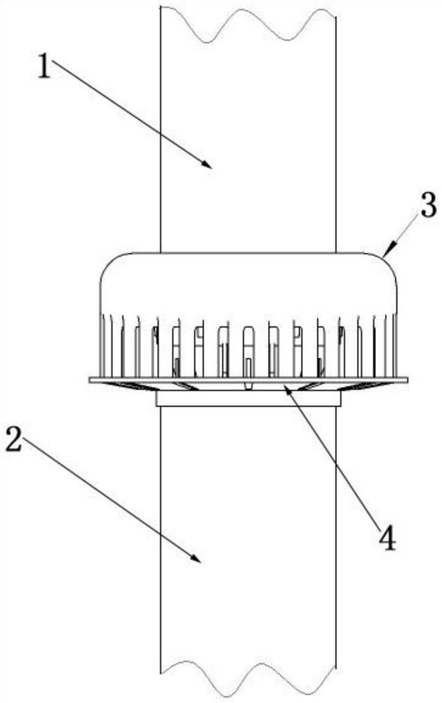
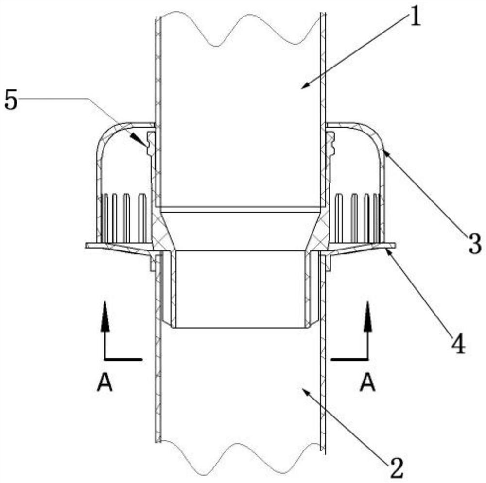
[0025] A rainwater drainage system standpipe embedded floor drain, including a protective cover 3, a water collecting tray 4, an upper standpipe 1, a lower standpipe 2, and a main body 5 for connecting the upper standpipe 1 and the lower standpipe 2, the main body 5 includes a large round pipe 51, a reducer and a small round pipe 52 arranged from top to bottom, and the lower end of the upper standpipe 1 is processed with an indentation structure matching the inner space of the main body 5, so that the lower end of the upper standpipe 1 is inserted into the main body within 5.

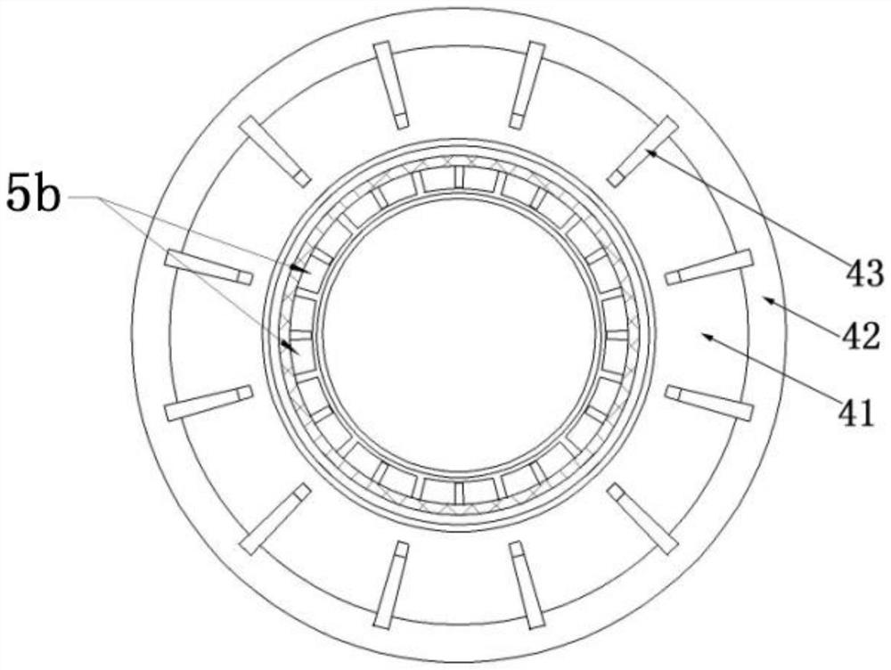
[0026] The outer side of the small round tube 52 is evenly spaced along the circumferential direction with a number of vertical grid plates 5b. When the small round tube 52 is inserted into the lower vertical tube 2, all the grid plates 5b on the outer side of the small round tube 52 are connected to the lower vertical tube. The inner walls of the tubes 2 are all ...


PUM


Abstract

This application discloses a pre-embedded floor drain in the standpipe of a rainwater drainage system, which includes a protective cover, a water collecting tray, an upper standpipe, a lower standpipe and a main body. Cooperate and insert in the main body; there are several vertical grid plates on the outside of the small round tube, and when the small round tube is inserted into the lower riser, all the grid plates on the outer side of the small round tube are in close contact with the inner wall of the lower riser The accumulated water enters the water collection tray after being filtered by the protective cover, and then flows into the lower standpipe through the water flow channel formed between the outer wall of the small round tube, the grid plate and the inner wall of the lower standpipe. The structure of the present application is simple, and the indented structure in the middle of the main body can accelerate the speed of water flow down, enhance the siphon effect, and enhance the drainage capacity of the floor drain. The middle part of the main body is provided with an indentation structure, the outer part of the main body is provided with baffles, and the grid plate structure is arranged outside the lower part of the main body, which can ensure that the gas is compensated into the lower riser when the flow is full, so that no negative pressure will be formed in the riser, thereby avoiding Sucking occurs.

Description

technical field [0001] The application relates to a rainwater drainage system of a building, in particular to a pre-buried floor drain in a standpipe of the rainwater drainage system. Background technique [0002] Nowadays, the policy of zero direct discharge of sewage is proposed, requiring rainwater and sewage to be discharged separately, and the rainwater drainage system needs to use a separate riser. The riser of the rainwater drainage system is generally installed in the corner of the balcony. Before the riser is installed, holes are reserved on the balcony structural plate, and the riser is sealed after the riser is installed. However, such a method is prone to cracks due to the shrinkage of the sealing material, which in turn causes water leakage. Contents of the invention [0003] In view of the above-mentioned technical problems existing in the prior art, the purpose of this application is to provide a pre-embedded floor drain for the standpipe of the rainwater d...

Claims


Application Information

Patent Timeline
Patent Type & Authority Patents(China)
IPC IPC(8): E03F5/04E04D13/08
CPCE03F5/0407E04D13/08E04D2013/0826E04D2013/0846
Inventor 朱海强范卫华冯济斌林鑫鑫
Owner LINHAI WEIXING NEW BUILDING MATERIALS CO LTD
Why Eureka
Try Eureka