
Magnetic assisted welding device and welding method

An auxiliary welding and connecting rib technology, applied in welding equipment, non-electric welding equipment, metal processing equipment, etc., can solve the problems of weakening the softening effect of the melting area, indentation of parts, and affecting the appearance quality of parts, etc., to increase the microhardness , Improve the effect of nugget shape

Active Publication Date: 2022-02-15
CRRC QINGDAO SIFANG CO LTD
View PDF5 Cites 0 Cited by
  • Summary
  • Abstract
  • Description
  • Claims
  • Application Information

AI Technical Summary

Problems solved by technology

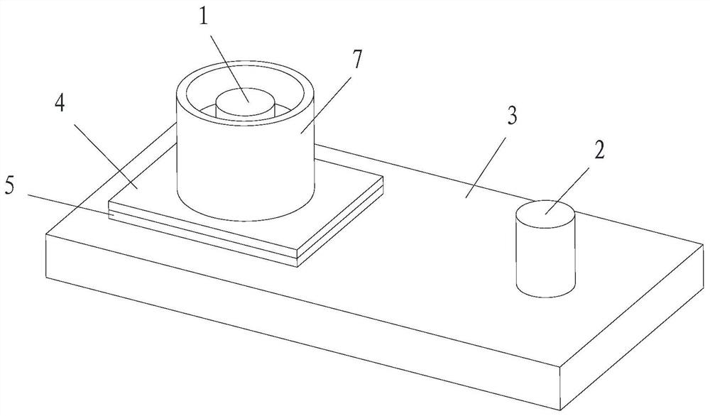
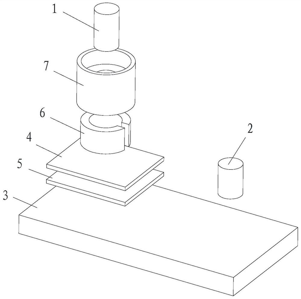
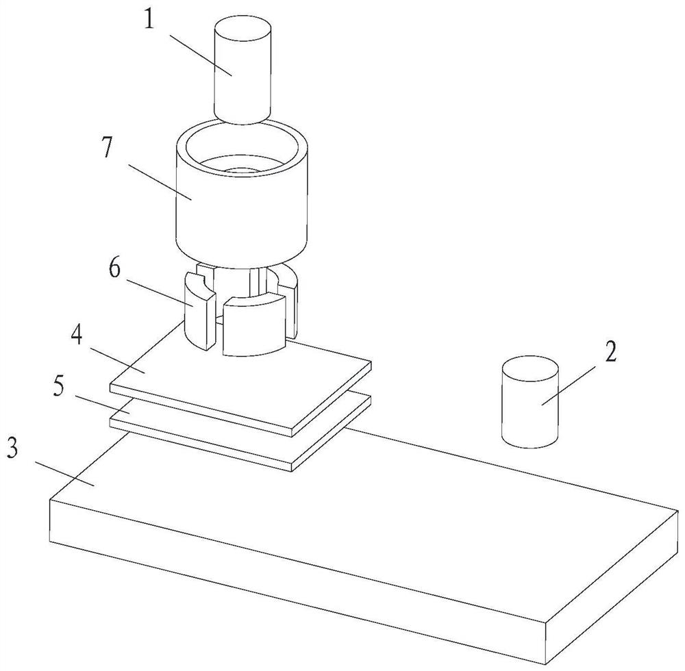
For this reason, the present invention proposes a magnetic-assisted welding device, which is used to solve the defect that there are indentations in the appearance welding of the parts in the prior art, which affects the appearance quality of the parts. By arranging magnetic units around the electrodes, the workpiece to be welded In the process, a magnetic field that stirs the nugget is generated inside the workpiece to be welded, and the interaction between the magnetic field and the welding current performs three-dimensional and real-time regulation on the molten metal in the welding area, thereby increasing the microhardness of the internal structure of the nugget and improving the nugget. Shape, greatly weaken the softening effect of the melting zone in the axial direction and reduce indentation
[0006] The present invention also proposes a magnetic-assisted welding method, which is used to solve the indentation existing in the appearance welding of the parts in the prior art, which affects the appearance quality of the parts, realizes the reduction of the indentation on the surface of the workpiece to be welded, and improves the shape of the nugget

Method used


Image

  • Magnetic assisted welding device and welding method
  • Magnetic assisted welding device and welding method
  • Magnetic assisted welding device and welding method

Examples


Embodiment Construction

[0065] In order to make the objects, technical solutions, and advantages of the present invention more clearly, the technical solutions in the embodiments of the present invention will be described in contemplation in the embodiment of the present invention. It is a part of the embodiments of the invention, not all of the embodiments. Based on the embodiments in the present invention, all other embodiments obtained without making creative labor without making creative labor.

[0066] In the description of the embodiments of the present invention, it is to be described in that the terms "center", "longitudinal", "horizontal", "upper", "lower", "front", "post", "left", "right" , "Vertical", "horizontal", "top", "bottom", "inside", "outside", etc., based on the orientation or positional relationship shown in the drawings, is only for ease of description SUMMARY OF THE INVENTION A simplified description, rather than indicating or implying that the device or element must have a specifi...


PUM


Abstract

Embodiments of the present invention provide a magnetic-assisted welding device and a welding method. The welding device includes: a first electrode, a second electrode, a substrate, a first workpiece to be welded, a second workpiece to be welded, and a magnetic unit; the first welder to be welded The piece and the second workpiece to be welded are stacked between the first electrode and the substrate; the second electrode and the second workpiece to be welded are in contact with the substrate; the magnetic unit ring is placed outside the first electrode; wherein, the first electrode and the second workpiece are in contact with the substrate. The surface of a workpiece to be welded abuts to form a nugget between the first workpiece to be welded and the second workpiece to be welded; the nugget is stirred by the magnetic unit. In the embodiment of the present invention, by arranging magnetic units around the electrodes, a stirring magnetic field that stirs the nugget is generated inside the workpiece to be welded, and the stirring magnetic field interacts with the welding current to perform three-dimensional and real-time control of the welding area, thereby increasing the number of nuggets in the mechanism. The microhardness of the organization improves the shape of the nugget, weakens the softening effect of the molten zone in the axial direction and reduces the indentation.

Description

Technical field [0001] The present invention relates to the field of welding techniques, and more particularly to a magnetic auxiliary welding device and a welding method. Background technique [0002] Welding is an important process in the manufacture of rail vehicles, and resistance point welding plays an important role in the welding of rail vehicles. The resistance point welder is a core connection process such as thin-walled structure such as the vehicle body due to its high efficiency, low cost, low cost, and easy to achieve automation. However, the resistance point welding head is prone to the joint softening and local overheating, resulting in excessive indentation, obvious burning traces, severely affecting the surface quality of the solder joint. For components (such as uncoated stainless steel subway, etc.) Time-consuming laborious and very limited [0003] Studies have shown that indiacts can be reduced to a certain degree by reducing current or increasing the welding...

Claims


Application Information

Patent Timeline
Patent Type & Authority Patents(China)
IPC IPC(8): B23K20/12B23K20/26
CPCB23K20/12B23K20/26
Inventor 韩晓辉徐野李刚卿叶结和刘勇
Owner CRRC QINGDAO SIFANG CO LTD
Learn More