Distributed multi-cyclone gas-water separation recycling device for tea fermentation

A tea fermentation and cyclone technology, which is applied in the field of tea fermentation, can solve the problems of heat waste and water mist not being recovered and recycled.

Inactive Publication Date: 2020-12-18
YUNNAN AGRICULTURAL UNIVERSITY
19 Cites 0 Cited by

AI-Extracted Technical Summary

Problems solved by technology

However, in these fermentation methods, it is necessary to humidify the tea leaves, and the water mist used for humidification will basically be heated. However, it is impossible for the tea leaves to ...

Method used

In the present invention, housing 304 is installed on the inner cavity inner wall of the gas outlet end of described gas outflow pipe 110 by bracket 332, and the left end sealing of installation housing 304 is installed with a water flow joint 319, connects water pipe 122 and water flow The joint 319 is sealed and connected; the atomizing nozzle 337 is installed at the right end of the installation housing 304 . The mandrel 306 is installed in the installation housing 304 by supporting the water-resistant bearing II 335, and the right end of the mandrel 306 is installed on the outlet end of the gas outflow pipe 110 by supporting the water-resistant bearing I 309, and the mandrel 306 is installed sequentially from left to right. Water pump impeller 305 , atomizing nozzle 337 , fan impeller 308 . The gas flows to the fan impeller 308 through the gas outflow pipe 110, the flow of the gas can drive the fan impeller 308 to rotate, the fan impeller 308 drives the mandrel 306 to rotate, and the mandrel 306 drives the water pump impeller 305 to rotate with it during the rotation p...

Abstract

The invention relates to a distributed multi-cyclone gas-water separation recycling device for tea fermentation, and belongs to the technical field of tea fermentation. The device comprises a gas outflow pipe (110), a water mist suction nozzle (111), a gas-water separation cyclone cylinder (112), a water flow collection heating box (118), a cyclone cylinder water outlet supporting pipe (116), a connecting water pipe (122), a water mist branch pipe (123), a water mist diversion cover (124), a water mist inflow pipe (127), a water mist diversion cone (128), a fan (310) and atomizing nozzles (337). After flowing through fermented tea leaves, automatic temperature and humidity control closed circulating water mist is sucked into the gas-water separation cyclone for gas-water separation, and after gas-water separation, water is collected into the water flow collection heating box to be heated and recycled; and then the gas is gathered to the gas outflow pipe through the gas suction outflowpipe, wherein water flow discharged by the gas outflow pipe and the water flow gathering heating box is gathered and atomized and then sprayed into the draught fan, so that the gas is scattered by thedraught fan to form fine water mist which enters the tea fermentation cabin to be used for tea fermentation, and therefore cyclic heating of the water mist in the fermentation cabin is achieved.

Application Domain

Fluid heatersMechanical apparatus +2

Technology Topic

Fermented teaTea leaf +4

Image

  • Distributed multi-cyclone gas-water separation recycling device for tea fermentation
  • Distributed multi-cyclone gas-water separation recycling device for tea fermentation
  • Distributed multi-cyclone gas-water separation recycling device for tea fermentation

Examples

  • Experimental program(1)

Example Embodiment

[0015]The technical solutions in the embodiments of the present invention will be clearly and completely described below in conjunction with the embodiments of the present invention and the accompanying drawings. Obviously, the described embodiments are only a part of the embodiments of the present invention, rather than all the embodiments. Based on the embodiments of the present invention, all other embodiments obtained by those of ordinary skill in the art without creative work shall fall within the protection scope of the present invention.
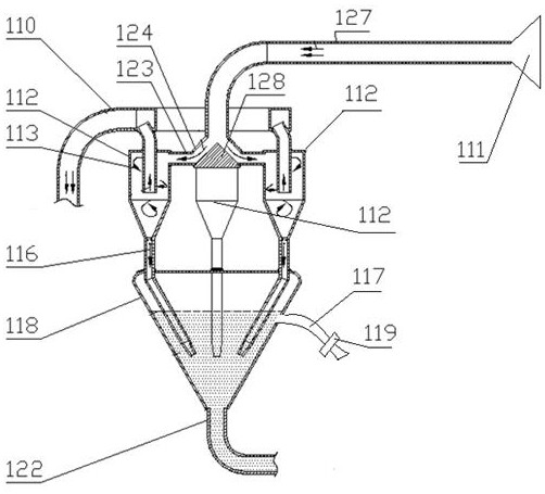
[0016]Such asfigure 1 ,2As shown, a distributed multi-cyclone gas-water separation and recycling device for tea fermentation includes a gas outflow pipe 110, a water mist suction nozzle 111, a gas-water separation cyclone 112, a water flow collection heating box 118, and a cyclone water outlet support pipe ( 116). Connecting the water pipe 122, the water mist branch pipe 123, the water mist shunt hood 124, the water mist inflow pipe 127, the water mist shunt cone 128, the fan 310, and the atomizing nozzle 337; the top of the water flow collecting and heating box 118 is connected The cyclone outlet support pipe (116), the cyclone outlet support pipe (116) supports the gas-water separation cyclone (112), the water mist branch pipe (123) and the water mist shunt cover 124, the bottom of the water mist shunt cover 124 A water mist splitting cone 128 is provided in the middle, and at least two water mist branch pipes 123 are provided on the water mist shunt cover 124. Each water mist branch pipe 123 is connected to a gas-water separation cyclone 112. The water blowing port of 112 is in communication with the water flow collecting and heating box 118; the top water inlet of the water mist shunt cover 124 is connected with the water mist inflow pipe 127, and the end of the water mist inflow pipe 127 is provided with a water mist suction nozzle 111; the air-water separation cyclone The air outlet of 112 is connected to the gas outlet pipe 110, the outlet of the gas outlet pipe 110 is connected to the air inlet of the fan 310, the water outlet end of the connecting water pipe 122 provided at the bottom of the water flow collecting heating box 118 extends into the outlet end of the gas outlet pipe 110, The water outlet end of the connecting water pipe 122 is provided with an atomizing nozzle 337; the air outlet of the fan 310 is connected to the aerosol outflow pipe 314. After the water mist in the fermentation chamber is inhaled through the water mist suction nozzle 111, it is returned to the water mist shunt cover 124 from the water mist inflow pipe 127, and the water mist is evenly divided to the water mist branch pipe 123 under the shunting action of the water mist shunt cone 128 Inside, the water mist is introduced into the gas-water separation cyclone 112 by the water-mist branch pipe 123 for gas-water separation. Such asimage 3 As shown, the gas-water separation cyclone 112 includes a cyclone pipe 140, a cyclone exhaust pipe 141, a cyclone cone 142, a cyclone outlet pipe 143, a cyclone bottom pipe 144, a cyclone bottom drainage cone 145, Cyclone top cover 147; the upper side wall of the cyclone tube 140 is provided with a water mist inlet 146, which is connected to the water mist branch pipe 123; the lower end of the cyclone tube 140 is connected to the cyclone cone 142, The cyclone outlet pipe 143 is vertically arranged at the bottom of the cyclone cone tube 142, the outlet of the cyclone outlet pipe 143 is connected to the cyclone bottom pipe 144, and the outlet of the cyclone bottom pipe 144 is connected to the bottom drainage cone 145 of the cyclone. The top of the tube 140 is provided with a cyclone top cover 147, the cyclone exhaust pipe 141 is provided in the middle of the cyclone top cover 147 and communicates with the cyclone tube 140, and the cyclone exhaust pipe 141 is connected to the gas outflow pipe 110. The water mist enters into the cyclone tube 140 through the water mist inlet 146, and the water mist spirally moves downward along the inner wall of the cyclone tube 140 to realize the separation of water and gas. In this process, the water flows down the inner wall of the cyclone tube 140. In the cyclone cone pipe 142, finally discharged into the water flow collecting heating box 118 through the cyclone outlet pipe 143, the cyclone bottom pipe 144, and the cyclone bottom drainage cone 145, while the gas is discharged into the cyclone exhaust pipe 141. The gas flows out of the pipe 110. The gas flowing out of the gas outflow pipe 110 flows into the inlet of the fan 310 through its inner cavity. At this time, the hot water heated by the water flow collecting and heating box 118 flows into the outlet end of the gas outflow pipe 110 through the connecting water pipe 122, because the end of the connecting water pipe 122 There is an atomizing nozzle 337, and the hot water is atomized and sprayed by the atomizing nozzle 337. The hot water is mixed with the gas at the outlet end of the gas outflow pipe 110 and sprayed into the fan 310. The air and the small water column are dispersed by the fan 310 to form a mist. Then the dispersed aerosol is sprayed into the fermentation chamber through the aerosol outflow pipe 314 to ferment the tea; in this process, spraying the aerosol on the fermented tea can make the fermentation of the tea more fully.
[0017]In the present invention, a casing 304 is installed on the inner wall of the gas outlet end cavity of the gas outlet pipe 110 through a bracket 332, and a water flow joint 319 is installed on the left end of the installation casing 304, and the water pipe 122 is connected to the water flow joint 319 to be sealed. Connection; the atomization nozzle 337 is installed at the right end of the mounting housing 304. A mandrel 306 is installed in the mounting housing 304 through a supporting water-resistant bearing Ⅱ335, the right end of the mandrel 306 is installed at the outlet end of the gas outflow pipe 110 through a supporting water-resistant bearing I309, and the mandrel 306 is sequentially installed from left to right Water pump impeller 305, atomization nozzle 337, fan impeller 308. The gas flows to the fan impeller 308 through the gas outflow pipe 110. The flow of the gas can drive the fan impeller 308 to rotate. The fan impeller 308 drives the spindle 306 to rotate, and the spindle 306 drives the water pump impeller 305 to rotate with it during the rotation. When water flows into the water pump impeller 305 from the water supply pipe 302, the rotation of the water pump impeller 305 will pressurize the water flow, so that the high-pressure water flow is directed to the atomizing nozzle 337, and the atomizing nozzle 337 is divided into a small water flow and directed to the rotating fan The impeller 308, the fan impeller 308 first disperses and mixes the gas flowing in the gas outflow pipe 110 and the water flowing in the atomizing nozzle 337 to form a gas mist. The water mist formed by the fan impeller 308 for the first time is dispersed in the high-speed rotating fan 310. Under the action, the second atomization is carried out to form a finer aerosol, and the particle size of the aerosol after the two atomization is smaller. This aerosol humidifies the tea and can ensure that the tea can be combined with the tea during the fermentation process. The water mist is in full contact to avoid the accumulation of too much water on the tea and affect the fermentation quality of the tea.
[0018]The bottom pipe 144 of the cyclone cylinder is arranged obliquely. The water flow collecting and heating box 118 can have a square structure, a circular structure or a tapered structure. When the water flow collecting and heating box 118 has a tapered structure, the cyclone bottom pipe 144 is installed obliquely. It is possible to prevent the cyclone bottom pipe 144 from interfering with the inner wall of the water flow collecting and heating box 118, resulting in poor drainage.
[0019] In the present invention, the closed-loop water mist with automatic temperature and humidity control after flowing through the fermented tea leaves is sucked into the gas-water separation cyclone for gas-water separation. After gas-water separation, the water is collected into the water flow collection heating box for heating and circulating use, and the gas is sucked The body outflow pipe is collected to the gas outflow pipe and the water flow discharged from the water flow collecting heating box is collected and atomized and sprayed into the fan. The fan is dispersed to form small water mist into the tea fermentation chamber for tea fermentation, thereby realizing the water mist in the fermentation chamber. The circulation heating is used.
[0020] Finally, it should be noted that the above preferred embodiments are only used to illustrate the technical solutions of the present invention, but not to limit them. Although the present invention has been described in detail through the above preferred embodiments, those skilled in the art should understand that it can be combined in form and Various changes are made to the details without departing from the scope defined by the claims of the present invention.

PUM

no PUM

Description & Claims & Application Information

We can also present the details of the Description, Claims and Application information to help users get a comprehensive understanding of the technical details of the patent, such as background art, summary of invention, brief description of drawings, description of embodiments, and other original content. On the other hand, users can also determine the specific scope of protection of the technology through the list of claims; as well as understand the changes in the life cycle of the technology with the presentation of the patent timeline. Login to view more.
Why Eureka
Try Eureka