Self-adaptive light source device

A light source device and self-adaptive technology, which is applied in the direction of instruments, calculations, character and pattern recognition, etc., can solve the problems of no light source equipment, poor experience, and inability to adapt to height, etc., to achieve the effect of improving interactive experience and scientific design

Active Publication Date: 2021-01-08
天津中科智能识别有限公司
View PDF13 Cites 0 Cited by
  • Summary
  • Abstract
  • Description
  • Claims
  • Application Information

AI Technical Summary

Problems solved by technology

[0004] Among them, the contact or short-distance iris recognition, due to the short distance, the light loss is small, the power of the light source is generally small, the light field is relatively uniform, and it is easy to meet; and the long-distance iris recognition has higher requirements for the light source. Within the range of identification safety, it is generally to increase the power, install it at an angle, and prevent reflections. However, although such a long-distance light source can meet the current identification environment requirements, the supplementary light area is limited, cannot be adjusted, and cannot adapt to height. It requires active cooperation and experience. Difference
[0005] With the development of iris recognition technology, higher requirements are put forward for the auxiliary light source, but there is no such light source device that can adapt to complex iris recognition conditions, which limits the long-distance iris (>2m) recognition, on-the-go Application and promotion of iris recognition and multi-target iris recognition technology

Method used


Image

  • Self-adaptive light source device
  • Self-adaptive light source device
  • Self-adaptive light source device

Examples


Embodiment Construction

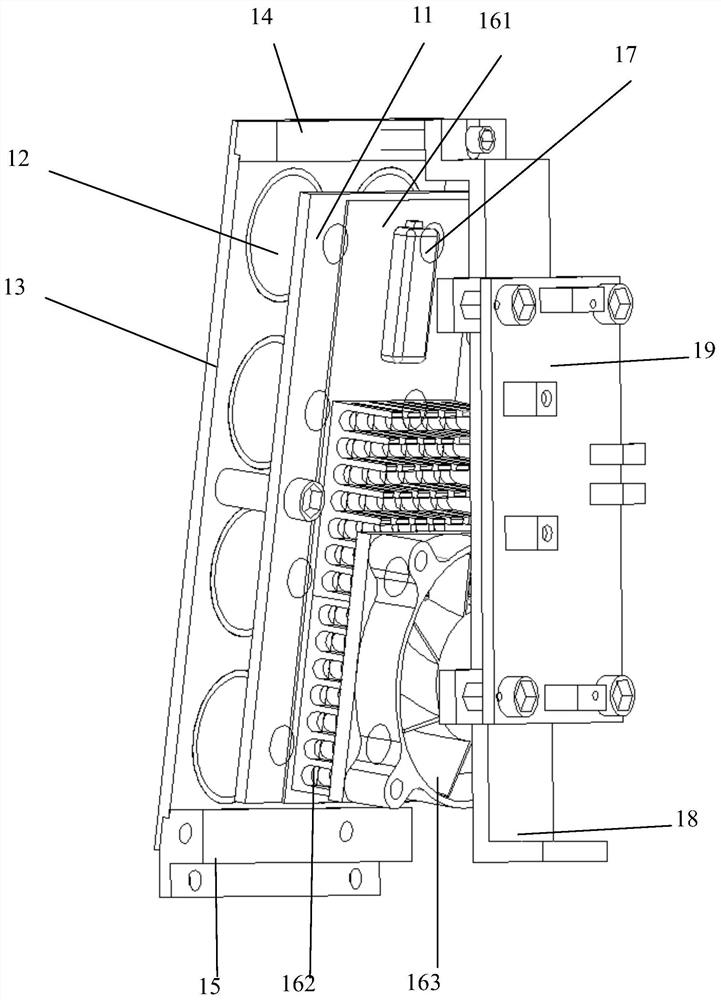
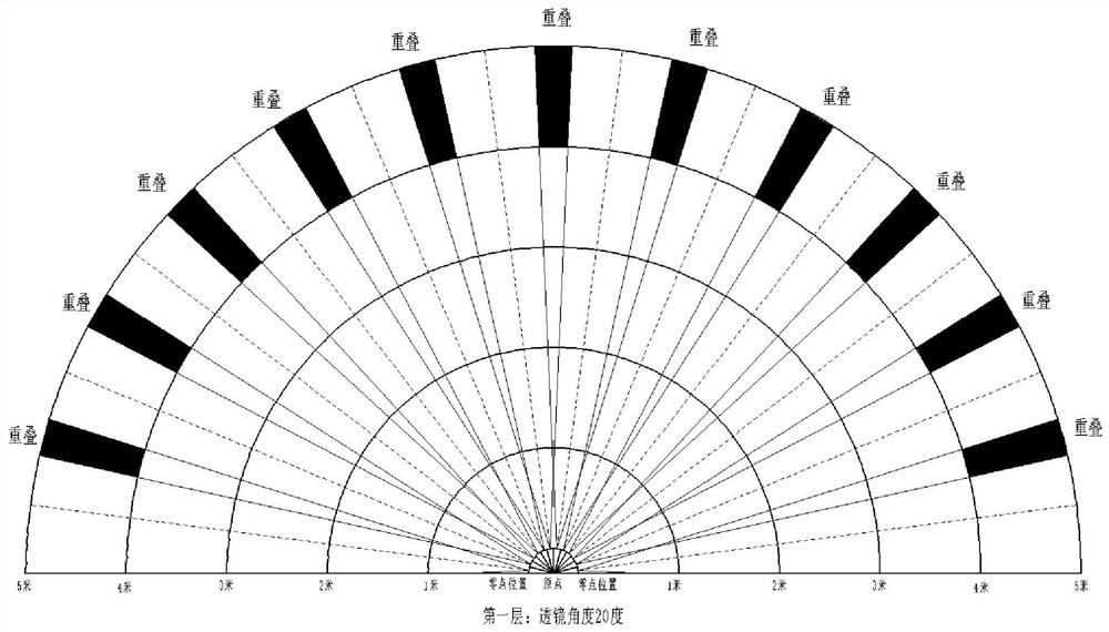
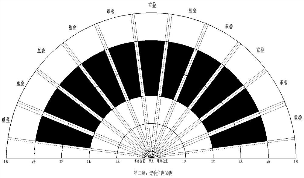
[0061] In order to make the technical means realized by the present invention easier to understand, the present application will be further described in detail below in conjunction with the accompanying drawings and embodiments. It should be understood that the specific embodiments described here are only used to explain the related application, not to limit the application. In addition, it should be noted that, for ease of description, only parts relevant to the present application are shown in the drawings.

[0062] It should be noted that, in the case of no conflict, the embodiments in the present application and the features in the embodiments can be combined with each other. The present application will be described in detail below with reference to the accompanying drawings and embodiments.

[0063] It should be noted that in the description of this application, the terms "center", "upper", "lower", "left", "right", "vertical", "horizontal", "inner", "outer", etc. The ...


PUM


Abstract

The invention discloses a self-adaptive light source device which comprises multiple layers of light sources. Each layer of light source comprises a plurality of light source modules, a light source substrate and a photoelectric control system; each light source module comprises a lamp bead plate; a lens cover plate is connected right ahead the lamp bead plate; a plurality of lamp bead lenses aremounted on the lens cover plate; an upper inclined connecting piece and a lower inclined connecting piece are respectively fixed at the upper and lower ends of the lens cover plate; a heat-conductingplate is fixed on the rear side surface of the lamp bead plate; a plurality of cooling fins and a temperature sensor are fixed on the rear side surface of the heat conduction plate; a cooling fan is mounted on the rear side of the cooling fin; a Z-shaped bracket is fixed on the rear side surface of the upper inclined connecting piece; the rear side surface of the Z-shaped bracket is fixedly connected with a lamp bead plate driver; and for each layer of light source, the light source modules are fixed to the side edge of the top of the light source substrate in a preset shape. The multiple layers of light sources are fixedly connected. According to the invention, the iris imaging light supplement problem in a complex scene can be effectively solved, and the light supplement requirements oflong distance, different orientations, different heights and multiple targets are met.

Description

technical field [0001] The invention relates to the technical field of adaptive light sources, in particular to an adaptive light source device. Background technique [0002] As a more secure biometric identification technology, iris recognition technology has become more and more widely used in the market with the development of mobile payment and intelligent society. Although the iris has unique advantages over other biological features such as face and gait, due to the tiny iris features, in order to obtain a better iris, it must be matched with high-performance hardware and a stable environment. [0003] Because the iris of Asians is inherently different from that of Europeans and Americans, special auxiliary light must be added to highlight the characteristics of the iris. Currently, near-infrared light in the 850nm band is mainly used in iris recognition. According to the different iris recognition equipment, the shape, size, power and installation angle of the auxil...

Claims


Application Information

Patent Timeline
Patent Type & Authority Applications(China)
IPC IPC(8): G06K9/00
CPCG06V40/18Y02B20/40
Inventor 孙哲南张堃博谭铁牛申振腾
Owner 天津中科智能识别有限公司
Why Eureka
Try Eureka