Water filtering device for fish tank

A technology of water quality filtration and fish tanks, which can be used in fish farming, agricultural fishing, climate change adaptation, etc., and can solve troubles and other problems

Inactive Publication Date: 2021-01-22
郭清
View PDF8 Cites 0 Cited by
  • Summary
  • Abstract
  • Description
  • Claims
  • Application Information

AI Technical Summary

Problems solved by technology

[0003] Most of the better fish tanks will be equipped with water quality filters. The filter pumps the water out of the fish tank, then filters it through the filter cotton, and then enters the fi

Method used


Image

  • Water filtering device for fish tank
  • Water filtering device for fish tank
  • Water filtering device for fish tank

Examples


Embodiment 1

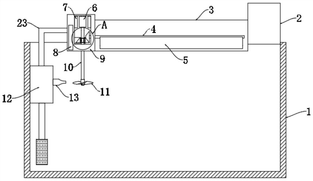
[0023] refer to Figure 1-3 , a fish tank water quality filtering device, comprising a fish tank body 1, a filter 12 is installed on the inner wall of the fish tank body 1, a filter box 3 is installed on the upper end of the fish tank body 1, and the filter 12 is composed of a silent water pump and an aeration pump, and the aeration pump Connected with an oxygen outlet 13, the filter 12 works uninterruptedly 24 hours a day, pumps the water in the fish tank body 1 into the water outlet pipe 23, then flows through the filter membrane 5 for filtration, and finally returns to the fish tank body 1 to realize circulation. The aeration pump provided on the 12 will also continuously pump the outside air into the water through the oxygen outlet 13.

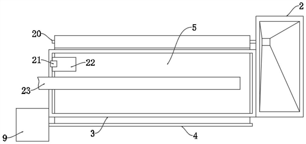
[0024] Both sides of filter box 3 are respectively fixed with device block 9 and fish food box 2, and the side wall of fish food box 2 is rotatably connected with unwinding shaft 20, and the side wall of device block 9 is rotatably connect...

Embodiment 2

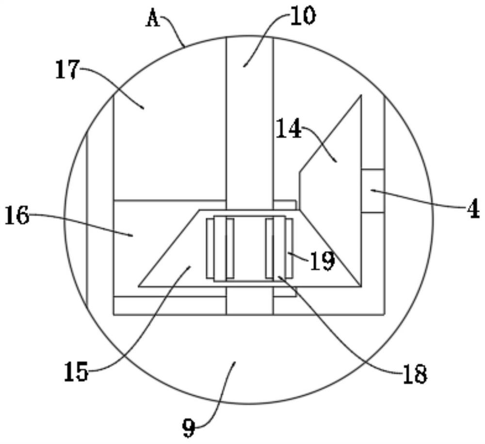
[0029] refer to Figure 4 The difference between this embodiment and Embodiment 1 is that the feeding mechanism includes a circular cavity 24 arranged in the bottom of the fish food box 2, and the circular cavity 24 is communicated with the inner bottom of the fish food box 2 through a feed port, and the unwinding shaft 20 The end of the fish food box 2 extends into the circular cavity 24 and is fixed with a plurality of feeding plates 25 at equal intervals. The end of the feeding plate 25 is in contact with the inner wall of the circular cavity 24, and the bottom of the fish food box 2 is provided with a discharge port communicating with the circular cavity 24 26.

[0030] In the present embodiment, a large amount of fish food is packed in the fish food box 2 at a time. When the filter membrane 5 is replaced, the service time of the filter membrane 5 is about one day, and the feeding of the fish is also fed once a day, so that During the rotation process of the reel 20, it d...


PUM


Abstract

The invention discloses a water filtering device for a fish tank. The water filtering device comprises a fish tank body, wherein a filter is installed on the inner wall of the fish tank body, a filtering box is installed at the upper end of the fish tank body, a device block and a fish food box are fixed to the two sides of the filtering box, an unwinding shaft is rotatably connected to the side wall of the fish food box, a winding shaft is rotatably connected to the side wall of the device block, a filter membrane is wound around the unwinding shaft, strip-shaped openings are formed in the opposite inner walls of the bottom of the filtering box, the filter membrane penetrates through the two strip-shaped openings to be connected with the winding shaft, a plurality of water outlets are formed in the bottom of the filtering box, a trigger mechanism is arranged inside the filtering box, the upper end of the filter is connected with a water outlet pipe extending to the position above thefiltering box, a mounting cavity is formed inside the device block, and a rotating rod is rotatably connected to the interior of the mounting cavity in a penetrating mode. The water filtering device is reasonable in structure, the water filtering device can automatically replace the filter membrane when the filter membrane needs to be replaced, and can feed fish food while the filter membrane is replaced.

Description

technical field [0001] The invention relates to the technical field of fish tanks, in particular to a water quality filter device for fish tanks. Background technique [0002] Fish tank, a kind of water tank containing live fish, the tank body is transparent, mostly made of glass, and can also be used to raise tropical fish or goldfish for ornamental purposes. The fish tank is not only the home of the fish, but also the life enjoyment of the family. [0003] Most of the better fish tanks will be equipped with water quality filters. The filter pumps the water out of the fish tank, then filters it through the filter cotton, and then enters the fish tank again to realize the cyclic filtration process. However, after the filter cotton is filtered for one day, it will be It needs to be taken out manually for cleaning, which is troublesome. Contents of the invention [0004] The purpose of the present invention is to solve the shortcomings in the prior art, and propose a fish ...

Claims


Application Information

Patent Timeline
IPC IPC(8): A01K63/04A01K61/85F03B13/00
CPCA01K63/042A01K63/045A01K61/85F03B13/00F05B2220/706Y02P60/60Y02A40/81
Inventor 郭清李继美
Owner 郭清
Why Eureka
Try Eureka