Flattening machine for material printing

A technology of flattening machine and printing mechanism, which is applied in the direction of printing machine, flat flat printing machine, printing, etc.

Active Publication Date: 2022-04-19
玉溪环球彩印纸盒有限公司
View PDF8 Cites 0 Cited by
  • Summary
  • Abstract
  • Description
  • Claims
  • Application Information

AI Technical Summary

Problems solved by technology

[0005] In order to overcome the shortcomings of the existing material flattening methods that need to manually load the material, manually move the material and manually flatten the material, the technical problem is to provide a method that can realize the material loading, transmission, printing and processing. Flattening machine for stamped material printing

Method used


Image

  • Flattening machine for material printing
  • Flattening machine for material printing
  • Flattening machine for material printing

Examples


Embodiment 1

[0065] A flattening machine for material printing, such as figure 1 As shown, it includes a bottom plate 1, a base 2, a cylinder 3, a push rod 4, a printing mechanism 5, and a printing pressure mechanism 6. A base 2 is provided on the left front side of the top of the bottom plate 1, and a cylinder 3 is arranged in the base 2. On the telescopic rod of the cylinder 3 A push rod 4 is connected, a printing mechanism 5 is connected between the push rod 4 and the base plate 1, a printing press mechanism 6 is connected between the front and rear sides in the middle of the bottom plate 1 top, and the parts of the printing press mechanism 6 are connected with the parts of the printing mechanism 5.

[0066] When people need to press the material, people first place the material under the parts of the pressing mechanism 6, and then people start the cylinder 3, and the telescopic rod of the cylinder 3 moves to the right to drive the push rod 4 to move to the right, and the push rod 4 move...

Embodiment 2

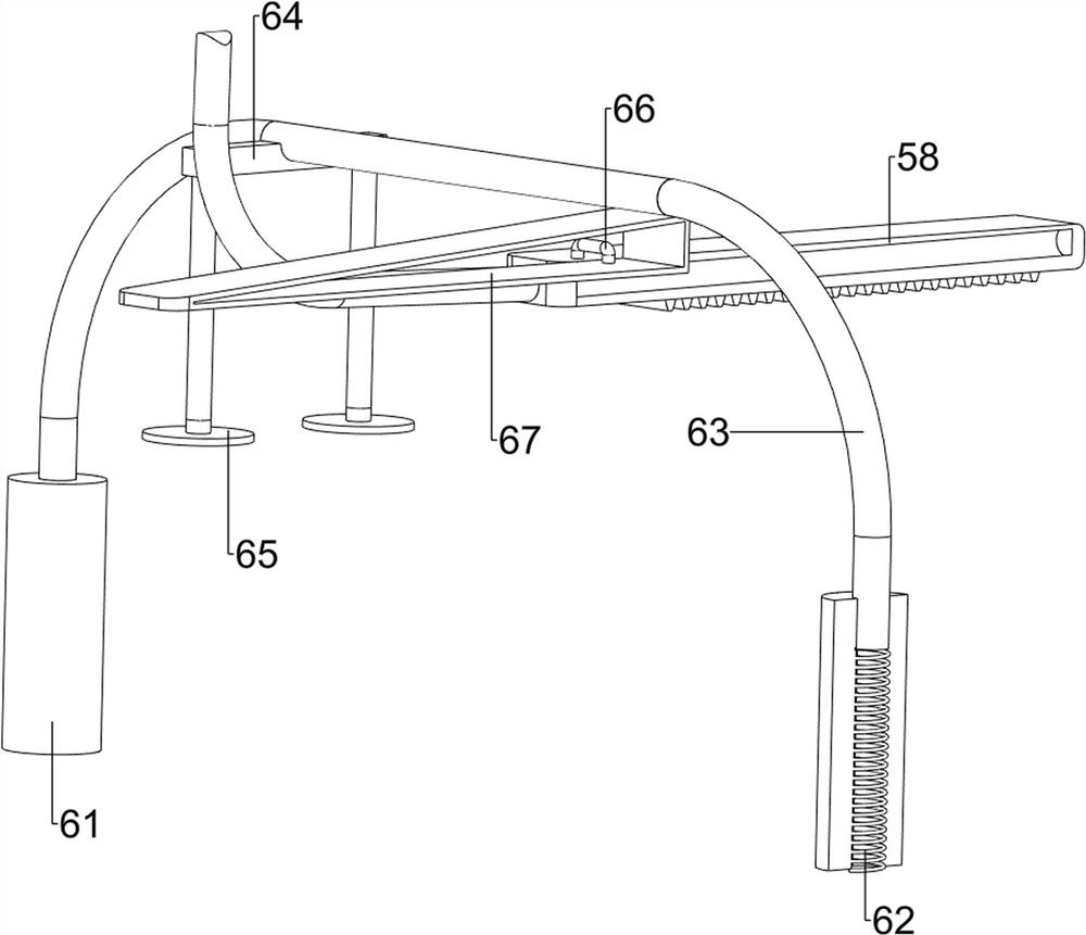
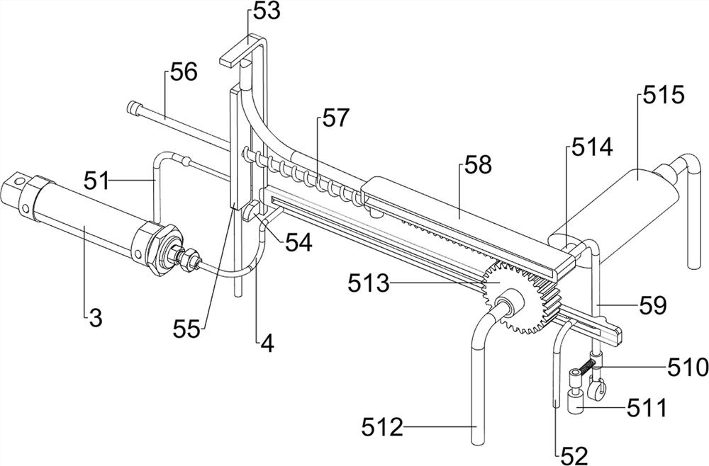
[0068] On the basis of Example 1, such as figure 2 and image 3 As shown, the printing mechanism 5 includes a first support 51, a second support 52, a first slide bar 53, an iron block 54, a third support 55, a second slide bar 56, a first spring 57, a rack bar 58, a wheel Frame 59, second spring 510, fixed seat 511, fourth support 512, full gear 513, cylindrical rod 514 and printer 515, base plate 1 top left front side is provided with first support 51, base plate 1 top right side is provided with second Support 52, the left side of the first support 51 is slidingly connected with the first sliding rod 53, the bottom of the first sliding rod 53 is provided with an iron block 54, the left front side of the bottom plate 1 is provided with a third support 55, and the third support 55 is located on the base 2 On the right side, the third support 55 middle part is slidably connected with a second slide bar 56, and the right part of the second slide bar 56 is connected with a rac...

Embodiment 3

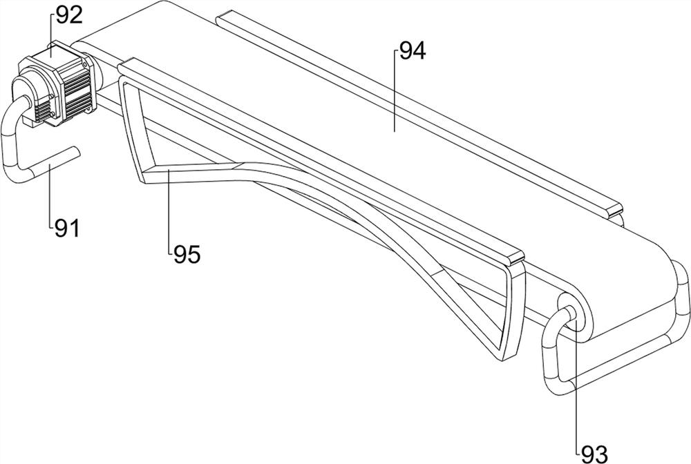
[0073] On the basis of Example 2, such as figure 1 , Figure 4 and Figure 5 As shown, also includes feeding mechanism 9, and feeding mechanism 9 includes the 6th support 91, intermittent rotating motor 92, runner 93, conveyer belt 94 and retaining frame 95, bottom plate 1 rear side top left and right sides are all provided with two A sixth support 91, the sixth support 91 on the right rear side is provided with an intermittent rotating motor 92, and the sixth support 91 on the same side is connected with a running wheel 93 in a rotating manner, and the output of the right running wheel 93 and the intermittent rotating motor 92 The shafts are connected, and a conveyor belt 94 is connected between the runners 93. Two material retaining frames 95 are arranged on the rear side of the top of the base plate 1, and the material retaining frames 95 are respectively located on both sides of the conveyor belt 94.

[0074] When people need to convey materials, people first place the m...


PUM


Abstract

The invention relates to a flattening machine, in particular to a flattening machine for material printing. Provided is a flattening machine for material printing that can realize material feeding, conveying, printing and embossing. A flattening machine for material printing, comprising a base plate and a base, the base is provided on one side of the top of the base plate; a cylinder, the base is provided with a cylinder; a push rod is connected to the telescopic rod of the cylinder; a printing mechanism, the push rod and the base plate A printing mechanism is connected between them; a printing mechanism, and a printing mechanism is connected between the front and rear sides of the top of the bottom plate, and the components of the printing mechanism are connected with the components of the printing mechanism. With the cooperation of the cylinder, push rod, printing mechanism, printing and pressing mechanism, material storage frame, opening and closing mechanism and feeding mechanism, the present invention can control material feeding, conveying materials, printing materials and pressing materials. Effect.

Description

technical field [0001] The invention relates to a flattening machine, in particular to a flattening machine for material printing. Background technique [0002] Printing is a common technology in our daily life. Many products are printed for aesthetics. Some items need to be flattened before printing to achieve a better printing effect. [0003] The existing method of flattening the material is to manually flatten the material, and people use a roller to roll the material back and forth to flatten. Flattened, and then people collect the flattened material. [0004] To sum up, it is necessary to develop a flattening machine for material printing that can realize loading, conveying, printing and embossing of materials, so as to solve the existing material flattening method that requires manual loading of materials , The problem of manual moving of materials and manual flattening of materials. Contents of the invention [0005] In order to overcome the shortcomings of the ...

Claims


Application Information

Patent Timeline
Patent Type & Authority Patents(China)
IPC IPC(8): B41F1/18B41F21/00B41F23/00
CPCB41F1/18B41F21/00B41F23/00
Inventor 方转娣
Owner 玉溪环球彩印纸盒有限公司
Why Eureka
Try Eureka