Emergency ventilation system for nuclear facility master control room

A technology of ventilation system and main control room, applied in ventilation system, auxiliary equipment of nuclear power plant, space heating and ventilation, etc., can solve problems such as power loss of power station, threat to power station safety, inability to activate ventilation system, etc., to improve safety factor and The effect of reliability, improving safety and stability, and improving gas safety

Inactive Publication Date: 2021-01-29
SANMEN NUCLEAR POWER CO LTD
View PDF6 Cites 1 Cited by
  • Summary
  • Abstract
  • Description
  • Claims
  • Application Information

AI Technical Summary

Benefits of technology

The technical effect of this innovation is that it allows for efficient cleaning indoor environments without requiring any external energy sources or equipment like electricity. It also includes various features such as filters, recoverers, pumps, fans, and other components used with an outdoor environment. Overall, these improvements enhance the performance and functionality of the overall ventilator system while reducing its risk of failure during maintenance operations.

Problems solved by technology

Technological Problem: The technical problem addressed in this patented text relates to ensuring proper maintenance of the primary control chamber (PC) during emergency situations where radiation exposure can cause harm or even result in failure of the PC due to insufficient cooling capacity caused by lack of electricity from outside sources such as diesel generators.

Method used


Image

  • Emergency ventilation system for nuclear facility master control room
  • Emergency ventilation system for nuclear facility master control room

Examples


Embodiment 1

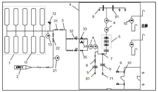
[0039]Example 1, such asfigure 1 As shown, it includes a high-pressure air storage device 1 and a delivery pipe 3. The high-pressure air storage device 1 is used to store high-pressure compressed gas. One end of the delivery pipe 3 is connected to the high-pressure air storage device 1 located outside the main control room 4, and the other end is connected to The air outlet 8 in the main control room 4 is connected, and the conveying pipeline 3 includes a passive valve 33 located in the main control room 4. The emergency ventilation system also includes a pressure relief device for releasing the pressure of the main control room 4. The high-pressure air storage device 1 is connected to the pressure-reducing module. The pressure-reducing module includes a pressure-reducing pipeline and a spare pressure-reducing pipeline connected in parallel with the pressure-reducing pipeline. The gas reduced by the pressure-reducing module passes through the air outlet 8 or the spare air outlet 61 ...


PUM


Abstract

The invention relates to an emergency ventilation system for a nuclear facility master control room. The emergency ventilation system comprises a high-pressure air storage device and a conveying pipeline, wherein the high-pressure air storage device is used for storing high-pressure compressed air, one end of the conveying pipeline is connected with the high-pressure air storage device located outside the main control room, the other end of the conveying pipeline is connected with an air outlet located in the main control chamber, the conveying pipeline comprises a passive valve located in themain control chamber, and the emergency ventilation system further comprises a pressure relief device used for relieving pressure of the main control chamber. According to the emergency ventilation system, power support does not needed, the risk of retention loss of the master control room is reduced, and the safety coefficient and reliability of the ventilation system of the master control roomare enhanced.

Description


Claims


Application Information

Patent Timeline
Owner SANMEN NUCLEAR POWER CO LTD
Why Eureka
Try Eureka