
A stainless steel outer surface wire drawing processing device

A wire drawing and outer surface technology, applied in metal processing equipment, grinding/polishing safety devices, manufacturing tools, etc., can solve the problem of unsightly stainless steel patterns and other problems, and achieve the effect of preventing excessive dust accumulation

Active Publication Date: 2022-06-07
杭州志恒链条制造有限公司
View PDF0 Cites 0 Cited by
  • Summary
  • Abstract
  • Description
  • Claims
  • Application Information

AI Technical Summary

Problems solved by technology

[0004] The purpose of the present invention is to solve the following disadvantages in the prior art. When the surface of stainless steel is wire-drawn, due to the large amount of dust and iron filings in the steel field, it often adheres to the surface of the stainless steel, which causes the influence of the pattern during the wire-drawing process, and thus the processed stainless steel A stainless steel outer surface wire drawing processing device proposed due to unsightly patterns that lead to reprocessing, or more importantly, lead to defective stainless steel tubes

Method used

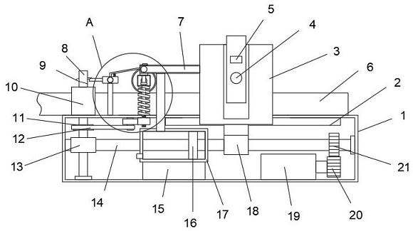
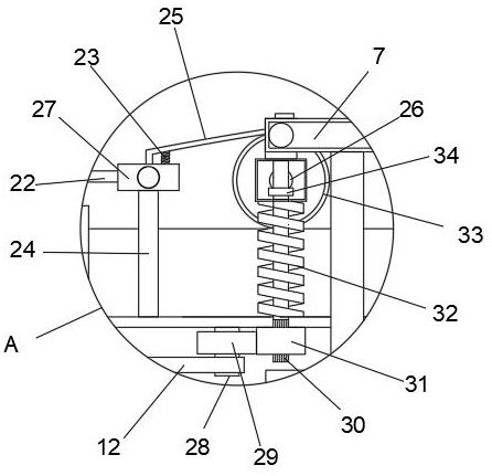
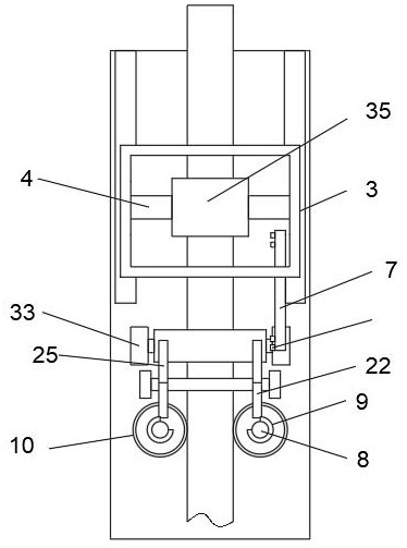

Image

  • A stainless steel outer surface wire drawing processing device
  • A stainless steel outer surface wire drawing processing device
  • A stainless steel outer surface wire drawing processing device

Examples


Embodiment Construction

[0025] The technical solutions in the embodiments of the present invention will be clearly and completely described below with reference to the accompanying drawings in the embodiments of the present invention. Obviously, the described embodiments are only a part of the embodiments of the present invention, but not all of the embodiments.

[0026] In the description of the present invention, it should be understood that the terms "center", "longitudinal", "lateral", "length", "width", "thickness", "upper", "lower", "front", " Rear", "left", "right", "vertical", "horizontal", "top", "bottom", "inside", "outside", "clockwise", "counterclockwise", etc. The relationship is based on the orientation or positional relationship shown in the drawings, which is only for the convenience of describing the present invention and simplifying the description, rather than indicating or implying that the device or element referred to must have a particular orientation, be constructed and operate...


PUM


Abstract

The invention discloses a stainless steel outer surface wire drawing processing device, which comprises a box body. Two drive rods are arranged horizontally in the box body. The two drive rods are arranged symmetrically. One end of the drive rod is provided with a worm thread , the worm thread on the drive rod is meshed with a worm wheel, and the worm wheel is fixedly connected with a rotating rod, and the rotating rod passes through the box and is connected with a round block, and a square steel plate is arranged between the two round blocks. , the box is fixedly connected with a second spring, and one end of the second spring away from the box is fixedly connected with a square shell, and a rack shaft is sleeved in the second spring, and the rack shaft passes through the square shell. The shell is fixedly connected with the second helical gear, and the present invention can beat the cleaning roller through the end of the slanting rod close to the cleaning roller, so that the dust on the cleaning roller can be knocked out repeatedly, and the gas sprayed out through the air nozzle on the air pipe cooperates , to reach the amount that the cleaning roller can be cleaned during work to prevent excessive dust accumulation on the cleaning roller.

Description

technical field [0001] The invention relates to the technical field of stainless steel processing, in particular to a stainless steel outer surface wire drawing processing device. Background technique [0002] In decoration, the most important thing is immediate beauty and practicality. Existing stainless steel is an indispensable building material in home decoration. Due to the requirement of beauty, stainless steel is often drawn before use to make it beautiful and smooth. [0003] However, the existing stainless steel wire drawing device, especially when the stainless steel surface is drawn, is often attached to the stainless steel surface due to the large amount of dust and iron filings in the steel field. In the process of wire drawing, the pattern is affected, so that the processed stainless steel will be re-processed due to the unsightly pattern, or more importantly, the stainless tube will be defective, so it cannot be used as a decoration. SUMMARY OF THE INVENTION...

Claims


Application Information

Patent Timeline
Patent Type & Authority Patents(China)
IPC IPC(8): B24B27/00B24B41/06B24B55/06
CPCB24B27/00B24B27/0092B24B41/06B24B55/06
Inventor 刘风胜
Owner 杭州志恒链条制造有限公司
Learn More