
Three-period cooperative multiple access cooperative transmission method

A cooperative transmission and time slot technology, applied in the direction of transmission system, digital transmission system, multiple use of transmission path, etc., can solve the problems that the transmission rate cannot achieve the desired effect at the same time, self-interference cannot be completely eliminated, and the transmission rate is lost.

Active Publication Date: 2021-02-05
UNIV OF ELECTRONICS SCI & TECH OF CHINA
View PDF4 Cites 0 Cited by
  • Summary
  • Abstract
  • Description
  • Claims
  • Application Information

AI Technical Summary

Problems solved by technology

[0005] If full-duplex technology is used, the self-interference caused by sending and receiving information on the same frequency at the same time
At the same time, due to the limitations of current technology, self-interference cannot be completely eliminated, so the system will be affected by residual self-interference
However, in the existing full-duplex cooperative transmission technology, each transmitter is assumed to use an ideal full-duplex technology without residual self-interference
Since the effect of residual self-interference is not considered, a part of the transmission rate is lost
[0006] From the above analysis, it can be seen that the existing transmitter cooperative transmission technology cannot achieve ideal results in terms of transmission rate at the same time. Therefore, it is necessary to conduct in-depth research on the mutual cooperative transmission technology of transmitters.

Method used


Image

  • Three-period cooperative multiple access cooperative transmission method
  • Three-period cooperative multiple access cooperative transmission method
  • Three-period cooperative multiple access cooperative transmission method

Examples


Embodiment

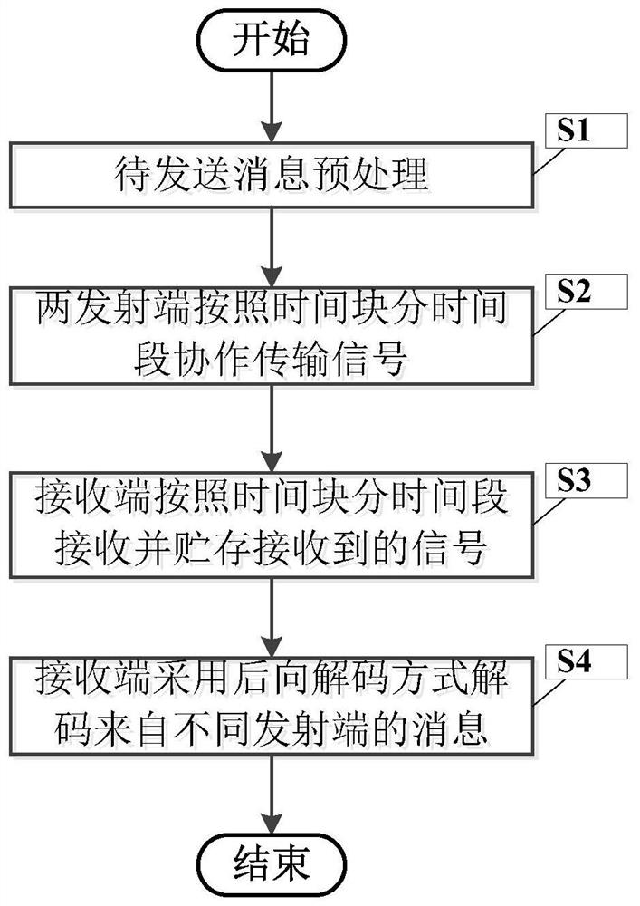
[0080] figure 1 It is a flowchart of a coordinated transmission method for three-period coordinated multiple access in the present invention.

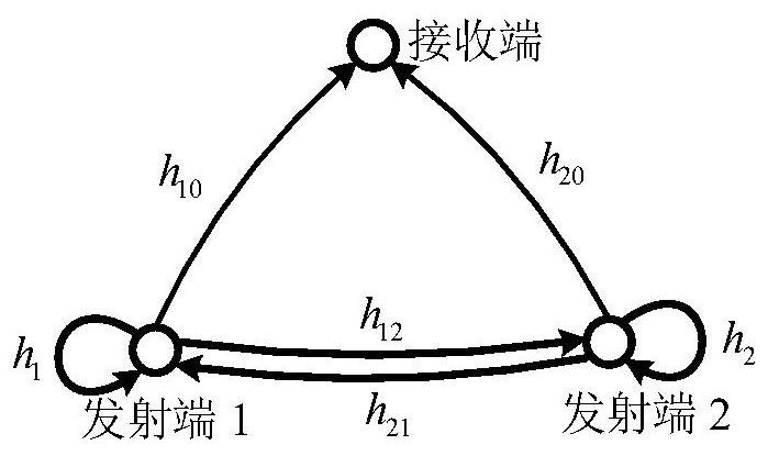
[0081] In this example, if figure 2 As shown, it is a network composed of two non-ideal full-duplex transmitters and one target node. For this network, we propose a three-period coordinated multiple access (3P-CMA) scheme. In this scheme, the transmitter adopts different power allocation methods in three periods.

[0082] Specifically, the 3P-CMA scheme is described as follows. In N time blocks, both transmitters transmit to the receiver at the same time. Each time block contains three time periods, numbered j=1,2,3. We use the transmitter Indicates another transmitter that cooperates with transmitter k. If k=1, then If k=2, then

[0083] Such as figure 1 As shown, below we describe in detail a coordinated transmission method of a three-period coordinated multiple access access method of the present invention, including t...


PUM


Abstract

The invention discloses a three-period cooperative multiple access cooperative transmission method, which comprises the following steps: at double transmitting ends, splitting a message to be transmitted according to time blocks and time periods and transmitting the split message to be transmitted to the transmitting ends, and then by the two transmitting ends, cooperatively transmitting signals according to the time blocks and the time periods; at a receiving end,receiving and storing the received signals according to time blocks and time periods, and then decoding messages from different transmitting ends in a backward decoding mode. In this way, the two transmitting ends communicate in a non-ideal full duplex mode, signals can be received and transmitted at the same frequency at the same time, and transmission is also affected by residual self-interference which is not completely eliminated.

Description

technical field [0001] The invention belongs to the technical field of wireless communication, and more specifically, relates to a coordinated transmission method for three-period coordinated multiple access. Background technique [0002] Transmitter cooperative signal transmission refers to a technology in which two or more transmitters cooperate to transmit signals to the receiver to increase the transmission rate. Cooperative signal transmission technology is a key technology in the field of wireless communication, and is widely used in cellular wireless communication. Compared with adding a relay device specially used for cooperation in the cellular network, the mutual cooperation of the transmitting end makes the cooperation behavior easier to occur, so that it has a wide range of application prospects. [0003] When considering two transmitters and one receiver, the current cooperative transmission of transmitters can be divided into two categories: half-duplex cooper...

Claims


Application Information

Patent Timeline
Patent Type & Authority Applications(China)
IPC IPC(8): H04B7/024H04L5/14
CPCH04B7/024H04L5/1469
Inventor 胡江平梁青鹏武艳芝李咏章沈昭宇
Owner UNIV OF ELECTRONICS SCI & TECH OF CHINA
Learn More