
A bridge multi-stage anti-seismic anti-overturning linkage device

A linkage device and anti-overturning technology, applied in bridges, bridge materials, bridge construction, etc., to achieve the effects of reducing excessive self-weight, preventing bridge overturning, and improving support efficiency

Active Publication Date: 2022-03-15
ANHUI UNIVERSITY OF ARCHITECTURE
View PDF6 Cites 0 Cited by
  • Summary
  • Abstract
  • Description
  • Claims
  • Application Information

AI Technical Summary

Problems solved by technology

[0005] The purpose of the present invention is to solve the problem that when using the existing traditional reinforcement method, the traditional reinforcement device can only carry out ordinary reinforcement on the bending resistance and shear bearing capacity of the bridge, and the reinforcement method is basically at the bridge pier, and proposes a bridge Multi-stage shockproof and anti-overturning linkage device

Method used


Image

  • A bridge multi-stage anti-seismic anti-overturning linkage device
  • A bridge multi-stage anti-seismic anti-overturning linkage device
  • A bridge multi-stage anti-seismic anti-overturning linkage device

Examples


Embodiment 1

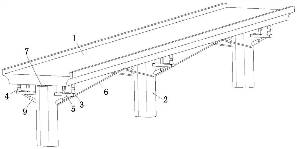
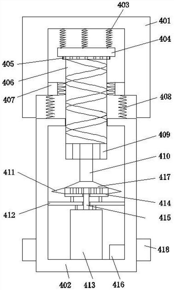
[0042] refer to Figure 1-12 , a multi-stage anti-seismic and anti-overturning linkage device for a bridge, comprising a bridge deck 1 and a single bridge pier 2, there are several single bridge piers 2 equidistantly arranged at the bottom of the bridge deck 1, and the two sides of the single bridge pier 2 are respectively fixedly connected with rigid extensions Plate 3, a vibration-damping support device 4 and an electromagnetic support device-5 are arranged between the top side of the rigid extension plate 3 and the bottom side of the bridge deck 1, and the vibration-damping support device 4 is located at the side of the electromagnetic support device-5 away from the single pier 2 On one side, a cable-stayed support device 6 is provided between the single pier 2 and the bottom edge of the bridge deck 1, and the top of the cable-stayed support device 6 is located vertically above the middle of two adjacent single bridge piers 2, A mercury switch one 7 and a mercury switch two...

Embodiment 2

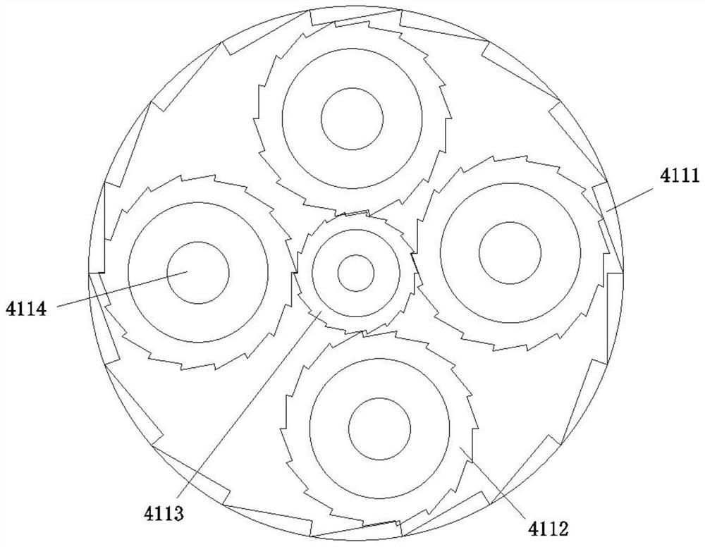
[0057] Such as image 3 As shown, this embodiment is basically the same as Embodiment 1. Preferably, the internal gears 4112 in the internal gear set 411 of the vibration-damping support device 4 mesh with each other, and the outer large gear ring 4111 drives the internal gear 4112 and the central shaft gear 4113 in turn.

[0058] In this embodiment, the mechanical energy generated by the upper bridge is amplified by the gear set 411 and then transmitted to the generator 413 .

Embodiment 3

[0060] Such as Figure 4 As shown, this embodiment is basically the same as Embodiment 1. Preferably, the inside of the electromagnetic box 504 is fixed with a cylindrical solid steel-505 with coils, and the material of the cylindrical solid steel-505 iron core is iron-aluminum alloy, and the internal coils are uniform. It is a copper coil, the number of turns is between 3000-7000, and the diameter is between 100-300mm.

[0061] In this embodiment, it is convenient for efficient transmission of electric current and generation of electromagnetic attraction and repulsion.


PUM


Abstract

The invention discloses a multi-stage anti-seismic and anti-overturning linkage device for a bridge, which comprises a bridge deck and a single bridge pier. There are several single bridge piers arranged equidistantly at the bottom of the bridge deck. Both sides of the single bridge pier are respectively fixedly connected with rigid extensions plate, a vibration-damping support device and an electromagnetic support device-1 are arranged between the top side of the rigid extension plate and the bottom side of the bridge deck, and the vibration-damping support device is located on the side of the electromagnetic support device-1 away from the single pier, and the single bridge pier A cable-stayed support device is provided between the pier and the bottom edge of the bridge deck, and the top of the cable-stayed support device is located vertically above the middle of two adjacent single bridge piers, and the bottom side of the bridge deck Mercury switch one and mercury switch two are installed. The device of the present invention realizes multi-level protection during the bridge overturning process, and improves the accuracy and accuracy of the bridge's earthquake resistance and overturning resistance when the bridge faces repeated loads, overload loads, and accidental natural conditions. Efficiency.

Description

technical field [0001] The invention relates to the technical field of anti-seismic reinforcement of bridges, in particular to a multi-stage anti-seismic and anti-overturning linkage device for bridges. Background technique [0002] The single column pier bridge is widely used in urban bridges and various complex terrains due to its advantages of small clearance under the bridge, simplicity and smoothness, beautiful appearance, strong adaptability, and good economy. However, in recent years, with the rapid development of my country's economy, the traffic flow and vehicle load have continued to increase, and vehicles have been overloaded and deflected, resulting in many overturning accidents in the use of single-pillar pier bridges, resulting in casualties and economic losses. And under some extreme natural conditions such as earthquake loads, ordinary reinforcement measures for bridges are difficult to play a role. [0003] The study found that the current highway bridge cod...

Claims


Application Information

Patent Timeline
Patent Type & Authority Patents(China)
IPC IPC(8): E01D19/00E01D19/02E01D19/04E01D22/00E01D101/30
CPCE01D19/00E01D19/02E01D19/048E01D22/00E01D2101/30
Inventor 王芳杜腾达石贤增吕天成刘甲宝马志平田佳王泽仪孙镇亮汪帆
Owner ANHUI UNIVERSITY OF ARCHITECTURE
Learn More