
Rapid plugging device for gas control reserved pipe

A technology of reserved pipe and gas, applied in gas discharge, mining equipment, sealing/sealing, etc., can solve the problems of bag puncture, loss of sealing effect, adhesion, etc.

Pending Publication Date: 2021-03-09
GUIZHOU INST OF TECH
View PDF11 Cites 0 Cited by
  • Summary
  • Abstract
  • Description
  • Claims
  • Application Information

AI Technical Summary

Problems solved by technology

[0003] After retrieval, the Chinese Patent Publication No. CN210087294U proposes a quick plugging device for the reserved pipe for gas control. There is a shortcoming in this patent. By injecting grout into the bladder, the bladder expands to block the reserved pipe, but the reserved After working for a long time, a lot of coal ash and some particles will adhere to the inner wall of the tube. After the bag expands, the particles may puncture the bag, thus losing the sealing effect

Method used


Image

  • Rapid plugging device for gas control reserved pipe
  • Rapid plugging device for gas control reserved pipe
  • Rapid plugging device for gas control reserved pipe

Examples


Embodiment 1

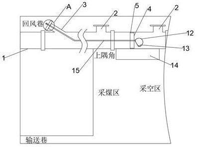
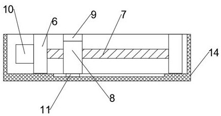
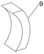
[0024] combine Figure 1-4 , a quick plugging device for reserved pipe for gas control, including reserved pipe 1, tee pipe 2, short connection pipe 3, plugging cover 16 and pouch 12, said reserved pipe 1 is equipped with tee pipe 2 and short pipe Take over the pipe 3, the short connection pipe 3 and the tee pipe 2 are all equipped with a blocking cover 16, the reserved pipe 1 is provided with a pouch 12, and one side of the pouch 12 is provided with a ring magnet 4, and the ring magnet 4 An annular rubber sleeve 5 is fixed on the outside of the magnet 4, and the annular rubber sleeve 5 is slidingly connected with the inner wall of the reserved tube 1. A protective shell 14 is installed on the outer side of the reserved tube 1 and is located at the ring magnet 4 and the pouch 12. The protective shell 14 is provided with a mounting block 6 fixed on the outside of the reserved pipe 1. There are two mounting blocks 6, and a threaded rod 7 is rotatably connected between the two mo...

Embodiment 2

[0031] combine figure 1 and Figure 5 , a quick plugging device for a reserved pipe for gas control, this embodiment further limits the invention on the basis of embodiment 1.

[0032] One end of the water pipe 15 and near the water source is equipped with a pressure gauge 17, and the pressure gauge 17 is set to facilitate the user to understand the water pressure in the bladder 12. When the water pressure reaches the rated pressure of the bladder 12, the water source is turned off to avoid the pressure of the bladder. Bag 12 is damaged.

[0033] Working principle: The motor 10 drives the threaded rod 7 to rotate, cooperates with the sliding limit of the threaded block 8 and the protective shell 14, so that the threaded block 8 moves, and the movement of the threaded block 8 drives the arc magnet 9 to move, and the arc magnet 9 is separated by the reserved The tube 1 and the ring-shaped rubber sleeve 5 are attracted to the ring magnet 4, thereby driving the ring magnet 4 to ...


PUM


Abstract

The invention discloses a rapid plugging device for a gas control reserved pipe. The rapid plugging device comprises the reserved pipe, a three-way pipe, a short connecting pipe, plugging covers and abag, wherein the three-way pipe and the short connecting pipe are mounted on the reserved pipe; the plugging covers are mounted on the short connecting pipe and the three-way pipe correspondingly; the bag is arranged in the reserved pipe; and an annular magnet is arranged on one side of the bag. According to the rapid plugging device, a motor drives a threaded rod to rotate, through sliding limiting of a threaded block and a protective shell, the threaded block moves to drive an arc-shaped magnet to move, the arc-shaped magnet and the annular magnet attract each other in the mode that the reserved pipe and an annular rubber sleeve are arranged between the arc-shaped magnet and the annular magnet, thus the annular magnet is driven to move, the annular magnet moves to drive the annular rubber sleeve to move, the annular rubber sleeve is in sliding fit with the inner wall of the reserved pipe, then particulate matter on the inner wall of the reserved pipe near the bag is scraped away, and thus the risk that when water is injected into the bag through a water pipe, the water reacts with a coagulator to bulge the bag, and then the bag makes contact with the particulate matter, so thatthe bag is punctured is avoided.

Description

technical field [0001] The invention relates to the technical field of gas control, in particular to a quick plugging device for a reserved pipe for gas control. Background technique [0002] In the process of underground coal mining, gas will be produced along with the mining of coal. The hidden danger of gas in the coal mining face is mainly in the upper corner, and a tee pipe is installed at a certain distance on the reserved pipe to extract gas from the upper corner of the coal mining face. When the coal mining face is mined to the position of the tee pipe, the blocking plate of the tee pipe will be opened. Since the three-way pipes in the goaf continuously draw air, an air flow area will be formed in the goaf between the air transported by the conveying roadway and each three-way pipe. With the increase of air, the residual floating coal in the goaf will intensify the oxidation of the floating coal in the goaf, and then spontaneous combustion will occur. In order to ...

Claims


Application Information

Patent Timeline
Patent Type & Authority Applications(China)
IPC IPC(8): E21B33/14E21F17/00E21F7/00
CPCE21B33/14E21F17/00E21F7/00
Inventor 许猛堂
Owner GUIZHOU INST OF TECH
Learn More