Polishing equipment with clamping function for hardware product machining

A kind of equipment and hardware technology, which is applied in the field of polishing equipment for hardware processing, can solve the problems of not being able to meet production and life, affecting the working efficiency of polishing equipment, and inconvenient use.

Inactive Publication Date: 2021-03-16
SUZHOU SINOYER MECHANICAL CO LTD
View PDF0 Cites 0 Cited by
  • Summary
  • Abstract
  • Description
  • Claims
  • Application Information

AI Technical Summary

Problems solved by technology

[0002] The auxiliary and accessory finished products used in daily life and industrial production of hardware products were mostly made of gold, silver, copper, iron, tin and other metal materials in the early days, hence the name. Now in addition to using various metal materials, they are also widely used Plastic, glass fiber and other non-metallic materials, hardware products need to be polished during the processing process, the current polishing equipment on the market still has various deficiencies, and cannot meet the needs of production and life;
[0003] For example, the specifications and sizes of hardware products vary greatly at present. When polishing and processing hardware products of different sizes, it is necessary to adjust the distance of the fixtures separately, so that the fixtures and hardware products of various specifications can be adapted and clamped stably. However, the traditional fixtures are more cumbersome to debug. It is time-consuming, affects the working efficiency of the polishing equipment, and is inconvenient to use. Therefore, we propose a polishing equipment for hardware processing with a clamping function.

Method used


Image

  • Polishing equipment with clamping function for hardware product machining
  • Polishing equipment with clamping function for hardware product machining
  • Polishing equipment with clamping function for hardware product machining

Examples


Embodiment

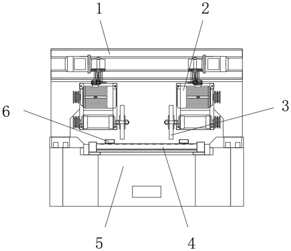
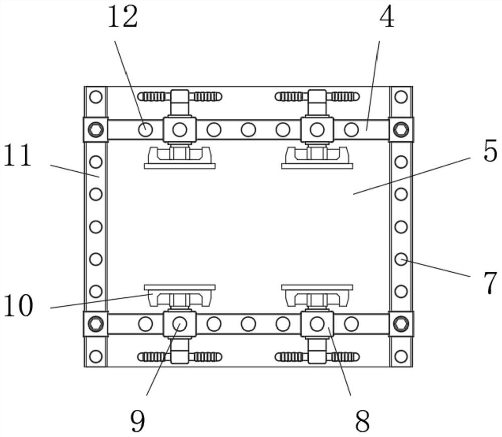
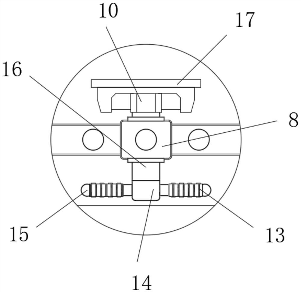
[0024] Please refer to figure 1 , figure 2 and image 3 As shown, the present invention provides a polishing device for processing hardware products with a clamping function, which includes a frame 1, a polishing device body 2 is fixedly connected to the top of the front end of the frame 1, and a polishing device body 2 is fixedly connected to the end of the polishing device body 2. The wheel 3 is fixedly connected with the working table 5 at the bottom of the front end of the frame 1, and the polishing wheel 3 is installed on the top of the working table 5, and the two ends of the top of the working table 5 are provided with guide rail rods 4, and the top of the guide rail rod 4 is provided with a movable seat 8. The inside of the movable seat 8 is provided with a threaded rod 16, the end of the threaded rod 16 is fixedly connected with a splint 10, and the surface of the end of the splint 10 is covered and fixed with a rubber pad 17. The seat 8 slides to the appropriate p...


PUM


Abstract

The invention discloses polishing equipment with the clamping function for hardware product machining. The polishing equipment comprises a rack, a polishing equipment body is fixedly connected to thetop of the front end of the rack, a polishing wheel is fixedly connected to the end of the polishing equipment body, a workbench is fixedly connected to the bottom of the front end of the rack, the polishing wheel is installed at the top of the workbench, guide rail rods are arranged at the two ends of the top of the workbench, movable bases are arranged at the top ends of the guide rail rods, lead screws are arranged in the movable bases in a penetrating mode, clamping plates are fixedly connected to the ends of the lead screws, and the surfaces of the ends of the clamping plates are fixedlycovered with rubber pads. The movable bases slide to the corresponding position along the guide rail rods according to the specification and size of a hardware product to be polished, the lead screwsrotate to be screwed into the movable bases to push the clamping plates to be further fixed, and the hardware product is more stable in the polishing machining process.

Description

technical field [0001] The invention relates to the technical field of hardware processing, in particular to a polishing device for processing hardware products with a clamping function. Background technique [0002] The auxiliary and accessory finished products used in daily life and industrial production of hardware products were mostly made of gold, silver, copper, iron, tin and other metal materials in the early days, hence the name. Now in addition to using various metal materials, they are also widely used Plastic, glass fiber and other non-metallic materials, hardware products need to be polished during the processing process, the current polishing equipment on the market still has various deficiencies, and cannot meet the needs of production and life; [0003] For example, the specifications and sizes of hardware products vary greatly at present. When polishing and processing hardware products of different sizes, it is necessary to adjust the distance of the fixtures...

Claims


Application Information

Patent Timeline
Patent Type & Authority Applications(China)
IPC IPC(8): B24B29/02B24B41/06B24B41/02
CPCB24B29/02B24B41/06B24B41/02
Inventor 于晓堃
Owner SUZHOU SINOYER MECHANICAL CO LTD
Why Eureka
Try Eureka