Workpiece polishing equipment

A technology for workpieces and equipment, applied in the field of workpiece polishing equipment, can solve problems such as injuries caused by operators, potential safety hazards, accidental collisions of workpieces, etc., and achieve the effects of high safety, prevention of injuries, and prevention of accidental collisions

Inactive Publication Date: 2018-04-03
HAINING JINXIN BEARING CO LTD
View PDF6 Cites 0 Cited by
  • Summary
  • Abstract
  • Description
  • Claims
  • Application Information

AI Technical Summary

Problems solved by technology

[0002] Polishing refers to the use of machinery, chemistry or electrochemistry to reduce the surface roughness of the workpiece to obtain a bright and flat surface. When polishing the workpiece, it is usually necessary to fix the workpiece first to prevent the workpiece from being polished. Shaking occurs when the workpiece is shaken, and then the polishing wheel is driven to move towards the workpiece, so as to polish the workpiece. However, in traditional workpiece polishing equipment, the polishing wheel is generally exposed, and it is easy to accidentally collide with the workpiece when the workpiece is advanced. In the process of fixing the workpiece, if the electric rotary machine is accidentally started, it is easy to cause injury to the operator. Therefore, the traditional workpiece polishing equipment has potential safety hazards

Method used


Image

  • Workpiece polishing equipment
  • Workpiece polishing equipment
  • Workpiece polishing equipment

Examples


Embodiment Construction

[0019] All features disclosed in this specification, or steps in all methods or processes disclosed, may be combined in any manner, except for mutually exclusive features and / or steps.

[0020] Any feature disclosed in this specification (including any appended claims, abstract and drawings), unless expressly stated otherwise, may be replaced by alternative features which are equivalent or serve a similar purpose. That is, unless expressly stated otherwise, each feature is one example only of a series of equivalent or similar features.

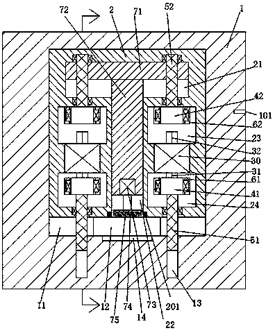
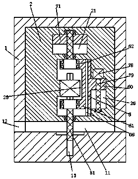
[0021] Such as Figure 1-3 As shown, a kind of workpiece polishing equipment of the present invention includes a frame 1, and a movable chamber 11 is arranged in the said frame, and a movable frame 2 can be installed up and down in the movable chamber 11, and the middle of the movable frame 2 is A first movable slot 22 with a lower port is provided at the position, and a second movable slot 21 communicating with the first movable slot 22 is a...


PUM


Abstract

Workpiece polishing equipment comprises a machine frame, a movable cavity is formed in the machine frame, a movable frame is up-down movably mounted in the movable cavity, a first movable groove witha port being close to the bottom is formed in the middle of the movable frame, a second movable groove communicating with the first movable groove is formed in the position, in the upper end of the first movable groove, of the movable frame, and a combined plate is up-down movably mounted in the second movable groove. An up-down slide column is up-down movably mounted in the first movable groove,and the upper end of the up-down slide column is fixedly connected with the combined plate, a first electric rotating machine is fixedly mounted at the lower end of the up-down slide column, and a polishing head is connected to the lower end of the first electric rotation machine. A polishing wheel is arranged in the polishing head, a plurality of concave holes are formed in the polishing head, aplurality of elastic steel balls matched with the concave holes are arranged on the polishing wheel, an upper fixedly mounting groove and a lower fixedly mounting groove are formed in the left and theright of the movable frame correspondingly, and a second electric rotation machine is fixedly mounted between the upper fixed mounting groove and the lower fixed mounting groove.

Description

technical field [0001] The invention relates to the field of polishing facilities, in particular to workpiece polishing equipment. Background technique [0002] Polishing refers to the use of machinery, chemistry or electrochemistry to reduce the surface roughness of the workpiece to obtain a bright and flat surface. When polishing the workpiece, it is usually necessary to fix the workpiece first to prevent the workpiece from being polished. Shaking occurs when the workpiece is shaken, and then the polishing wheel is driven to move towards the workpiece, so as to polish the workpiece. However, in traditional workpiece polishing equipment, the polishing wheel is generally exposed, and it is easy to accidentally collide with the workpiece when the workpiece is advanced. In the process of fixing the workpiece, if the electric rotary machine is accidentally started, it is easy to cause injury to the operator. Therefore, the traditional workpiece polishing equipment has potential...

Claims


Application Information

Patent Timeline
Patent Type & Authority Applications(China)
IPC IPC(8): B24B29/02B24B47/12B24B41/00B24B41/06
CPCB24B29/02B24B41/00B24B41/06B24B47/12
Inventor 蔡玉君
Owner HAINING JINXIN BEARING CO LTD
Why Eureka
Try Eureka