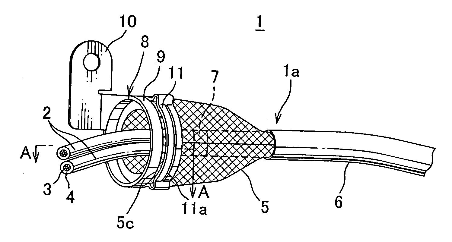
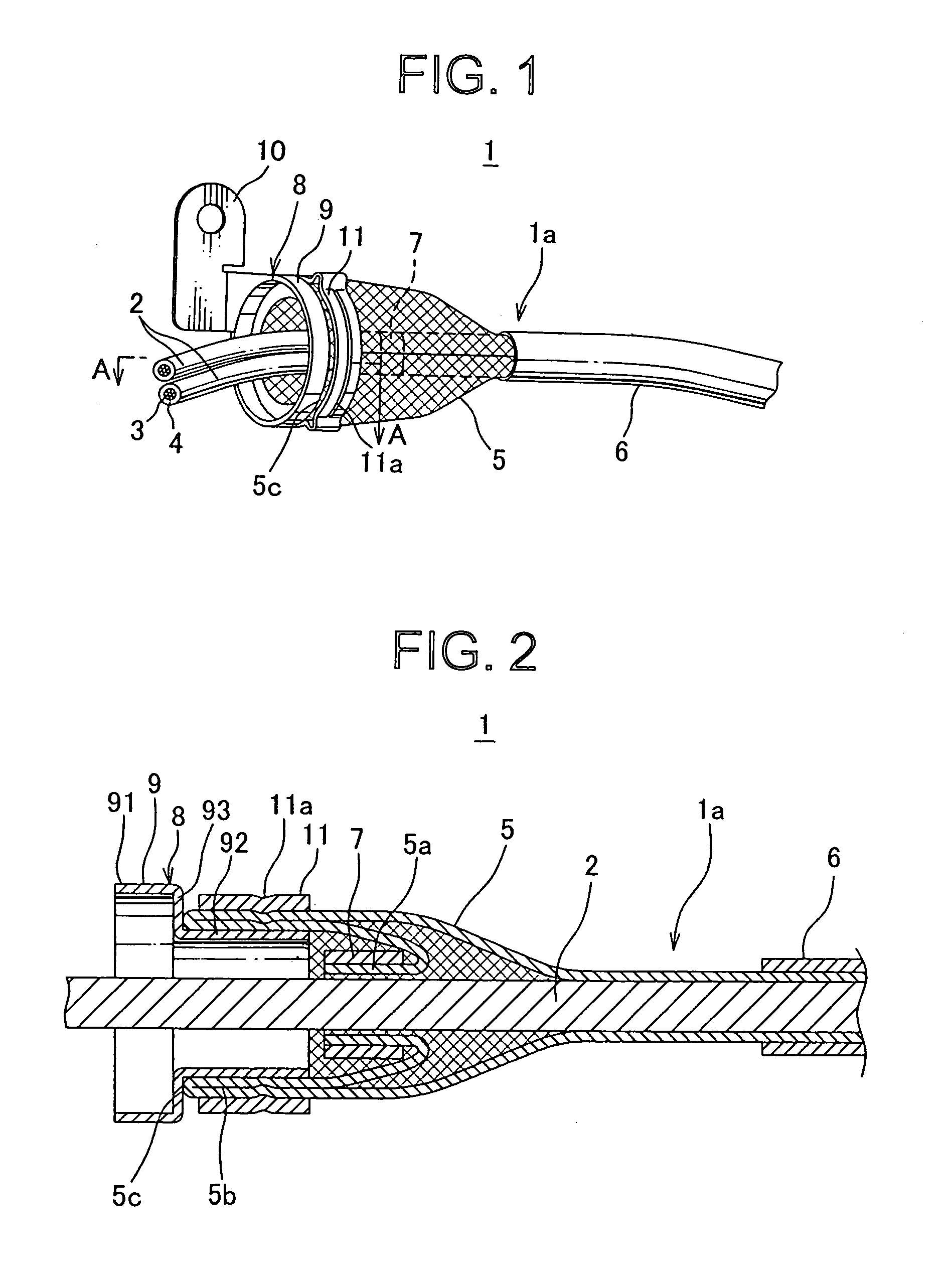
[0015]The shield wire according to the present invention includes the electric wire, the cylindrical braid covering the electric wire, the
adhesive tape wound around the top of the braid for preventing unbraiding the top of the braid, the set of inner and outer
metal ring brackets. The top of the braid is pushed from the top toward the far-side to be overlapped of the braid so as to fold the part from the top into the braid itself to form the overlap portion, and the set of inner and outer
metal ring brackets clamps the overlap portion so as to maintain the overlap portion in the cone shape, in which the top is located. Thereby, terminal treatment of the braid for attaching the set of inner and outer
metal ring brackets at the overlap portion can be processed easily and safely, and efficiency of processing the terminal treatment can be improved. In addition, the processing can be automated by an apparatus, so that efficiency of the processing can be more improved. The shield wire has triply overlapped braid at the end of the braid by the top and folded portion, so that density of braid is increased and shield performance will be improved. According to the shield wire, the overlap portion is clamped between the set of inner and outer metal ring brackets, so that without unbraiding the overlap portion, the overlap portion can be arranged uniformly about density of the braid around the overlap portion between the set of inner and outer metal ring brackets. Thus, shield performance decreased by decreasing braid density by the cone shape can be prevented by the overlap portion. Unbraiding at the top and the top
coming out of the overlap portion can be prevented in a long period by winding the
adhesive tape around the top of the braid.
[0016]The method for processing terminal treatment of braid of the shield wire according to the present invention includes steps of winding the
adhesive tape around the top of the cylindrical braid covering the electric wire, pushing the top from the top toward the far-side to be overlapped of the braid so as to fold the part of the braid from the top into the braid itself to form the overlap portion, forming approximately into the cone shape, in which the top is located, and attaching the set of metal ring brackets by clamping the formed overlap portion. Thereby, unbraiding the top of the braid in a process of pushing the top is prevented by winding the tape. Thus, the top can be pushed easily from the top toward the far-side of the braid. A folding line at an end of the overlap portion is positioned in the same plane, so that the overlap portion and the set of metal ring brackets can be positioned securely in a process of attaching the set of metal ring brackets. Thus, the overlap portion can be clamped between the set of metal ring brackets, and a yield of products can be improved. Thereby, terminal treatment of the braid for attaching the set of metal ring brackets at the overlap portion can be processed easily and safely, and efficiency of processing the terminal treatment can be improved. In addition, the processing can be automated by an apparatus, so that efficiency of the processing can be more improved.
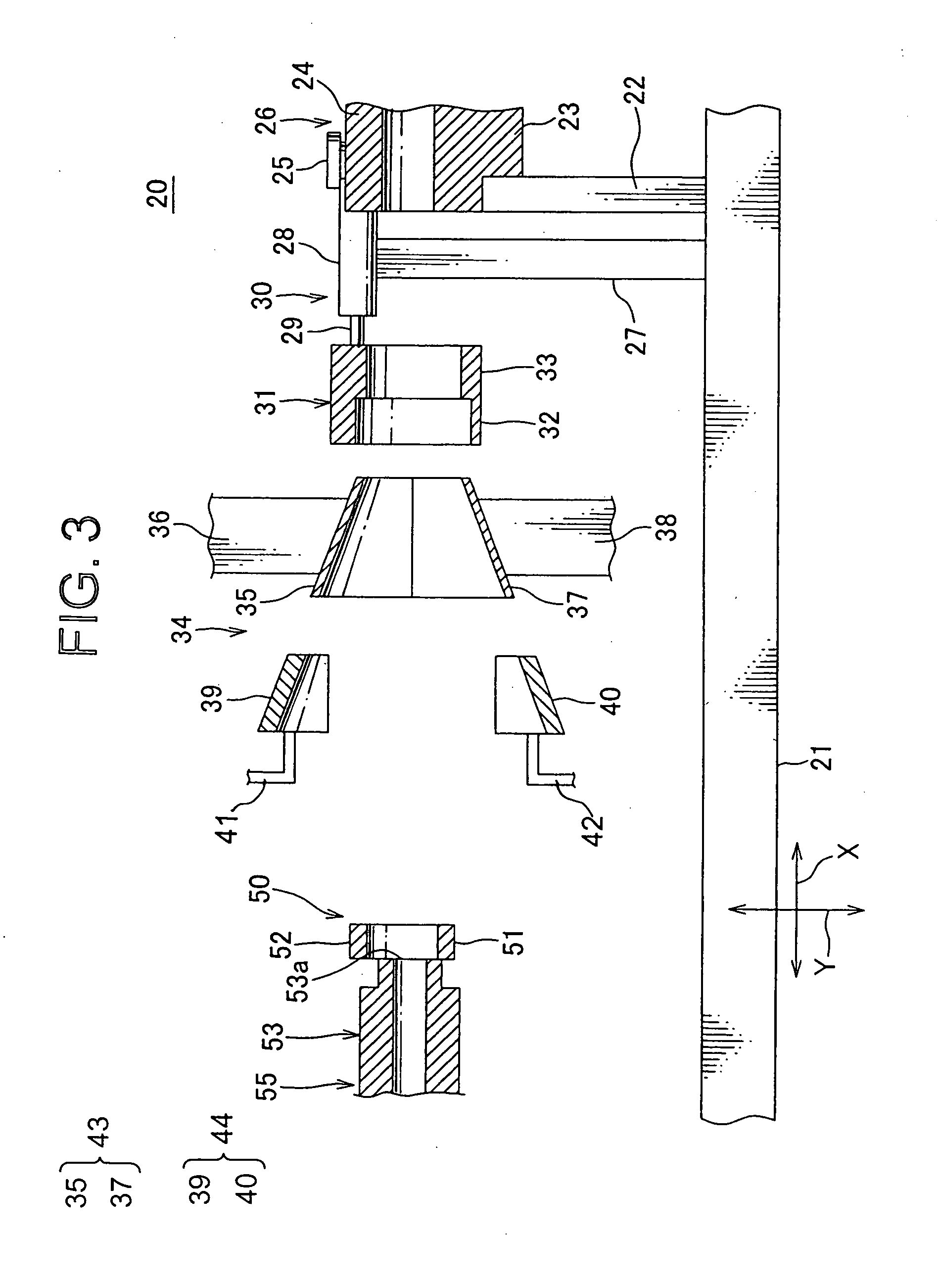
[0017]The apparatus for processing terminal treatment of braid of the shield wire according to the present invention includes the first hold unit holding the top of the braid covering the electric wire, the second hold unit holding the far-side of the braid from the top, the push unit pushing the top from the top toward the far-side of the braid so as to fold the part of the braid from the top into the braid itself to form the overlap portion, and the forming unit forming the overlap portion approximately into the cone shape, in which the top is located. The apparatus for processing terminal treatment having the simple structure can automate the terminal treatment of the braid. A folding line at an end of the overlap portion is positioned in the same plane, so that the overlap portion and the set of inner and outer metal ring brackets can be positioned securely in a process of attaching the set of inner and outer metal ring brackets. Thus, the overlap portion can be clamped between the set of inner and outer metal ring brackets, and a yield of products can be improved. Thereby, terminal treatment of the braid for attaching the set of inner and outer metal ring brackets at the overlap portion can be processed easily and safely, and efficiency of processing the terminal treatment can be improved.
[0018]In the apparatus for processing terminal treatment of braid of the shield wire mentioned above, the forming unit includes the plurality of outer forming pieces structuring the outer forming die having the truncated cone shape of the decreasing inner
diameter along the direction from the top toward the far-side of the braid for positioning the overlap portion in the outer forming die, the drive unit moving the plurality of outer forming pieces close to and apart from each other in the radial direction perpendicular to the direction from the top toward the far-side of the braid, the plurality of inner forming pieces structuring the inner forming die pressing the overlap portion against an inner surface of the outer forming die, and a support unit supporting the plurality of inner forming pieces freely in the radial direction and the direction from the top toward the far-side of the braid. Thereby, a series of processing the terminal treatment of the braid can be processed continuously so that process tact time is short and an apparatus for processing terminal treatment of the braid with a
small foot print can be provided. Then, the process terminal treatment can be more improved about its efficiency.
[0019]The apparatus for processing terminal treatment of braid of the shield wire mentioned above further includes the bracket hold unit supporting movably the set of inner and outer metal ring brackets between the position, in which the far-side to be overlapped of the braid held by the first hold unit and the second hold unit is located in the set of inner and outer metal ring brackets, and another position, in which the overlap portion held by the second hold unit is located in the set of inner and outer metal ring brackets, and the transfer unit positioning the bracket hold unit at the position until the overlap portion is formed securely, and after the overlap portion is formed, transferring the bracket hold unit at the another position. Thereby, a series of processing the terminal treatment of the braid can be processed continuously so that process tact time is short and an apparatus for processing terminal treatment of the braid with a
small foot print can be provided. Then, the process terminal treatment can be more improved about its efficiency. Furthermore, the set of inner and outer metal can be positioned around the overlap portion so as to prevent from deforming the overlap portion.

