Laser machine, laser machine system

a laser machine and tool holder technology, applied in the field of laser machines, can solve the problems of tool holder falling and breaking, complicated and time-consuming removal process of tool holder from laser machine, etc., and achieve the effect of easy and safe handling of tool holder and easy and safe assembling and disassembly process

Active Publication Date: 2016-02-02
GF MACHINING SOLUTIONS AG
View PDF14 Cites 0 Cited by
  • Summary
  • Abstract
  • Description
  • Claims
  • Application Information

AI Technical Summary

Benefits of technology

[0006]The foregoing object is achieved by a laser machine which allows for an easy and safe handling of the tool holder and in particular an easy and safe assembling and disassembling process.

Problems solved by technology

With known laser machines the process of removing the tool holder from the laser machine is either complicated and time consuming or it is unsafe, such that the tool holder can fall and break.

Method used


Image

  • Laser machine, laser machine system
  • Laser machine, laser machine system
  • Laser machine, laser machine system

Examples


Embodiment Construction

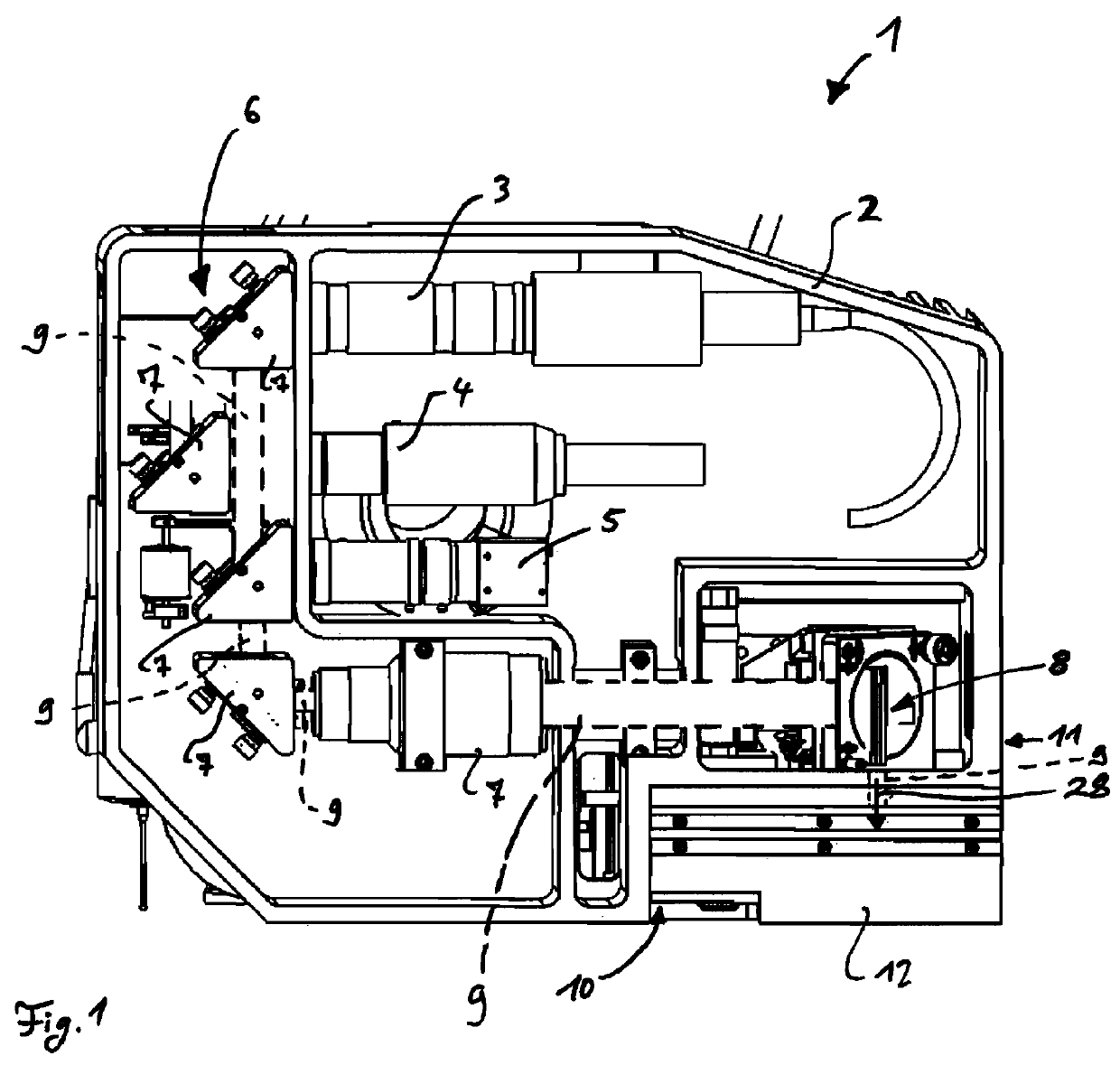
[0030]FIG. 1 shows a schematic side view of a laser machine 1 for drilling, cutting, welding or engraving an object. The laser machine 1 comprises a housing 2 in which two laser light sources 3 and 4 are arranged to generate a laser beam 9 which is used for the drilling, cutting, welding or engraving process. Optionally, a camera 5 is provided in order to enhance operation of the laser machine 1. The laser machine 1 further includes an optical system 6 arranged within the housing 2 to guide and manipulate the generated laser beam 9. The optical system 6 comprises a couple of guiding modules 7, each containing at least one guiding element such as a mirror or a lens. The optical system 6 further comprises a galvanometric laser head 8 to which the generated laser beam 9 is directed. One or more of the guiding modules 7 can be moved such that it intersects the laser beam 9 manipulated by the previous module 7 or to clear the way for the generated laser beam 9 as shown in FIG. 1.

[0031]At...


PUM

PropertyMeasurementUnit
movementaaaaaaaaaa
shapeaaaaaaaaaa
magneticaaaaaaaaaa

Abstract

A laser machine (1), in particular for drilling, cutting, welding or engraving, comprising at least one laser light source (3,4,5) for generating a laser beam (9) and an optical system (6) to guide and / or manipulate the laser beam (9), whereby the optical system (6) comprises at least one tool (23), in particular an optical lens (24) or a nozzle, which is attached to an interchangeable tool holder (12). It is provided that a guiding system (16) for the tool holder (12) is configured such that the tool holder (12) can only be slid sideways into or out of a tool bay (10) provided by the laser machine (1), the guiding system (16) comprising an operable locking system (37) for restraining the movement of the tool holder (12) in the tool bay (10).

Description

BACKGROUND OF THE INVENTION[0001]The present invention relates to a laser machine, in particular for drilling, cutting, welding or engraving, comprising at least one laser light source for generating a laser beam and an optical system to guide and / or to manipulate the laser beam, whereby the optical system comprises at least one tool, in particular an optical lens or nozzle, which is attached to or carried by an interchangeable tool holder.[0002]The present invention further relates to a laser machine system with a laser machine as described above.[0003]Laser machines as described above are well known in the art. A laser light source is used to generate a laser beam which is guided and manipulated by an optic system, such that it is directed onto an object to be machined. The optic system comprises, for example among other things, such as guiding mirrors or the like, at least one tool which also guides or manipulates the laser beam and which can be interchanged in order to adapt the...

Claims


Application Information

Patent Timeline
Patent Type & Authority Patents(United States)
IPC IPC(8): B23K37/00B23K26/00B23K37/02B23Q3/155G02B7/14B23K26/38B23K26/36B23K26/20B23K26/14B23K26/04B23K26/06
CPCB23K26/382B23K37/00B23K37/02B23Q3/155G02B7/14B23K26/1482B23K26/20B23K26/36B23K26/0648B23K26/00B23K26/0066B23K26/043B23K26/064B23K26/38B23K26/21B23K26/352
Inventor PAGANELLI, DINO, CATALDO
Owner GF MACHINING SOLUTIONS AG
Why Eureka
Try Eureka