Panel turning apparatus

a turning apparatus and turning plate technology, applied in the direction of grinding machine components, manufacturing tools, transportation and packaging, etc., can solve the problems of slowing down the overall process of manufacturing the panel, affecting the overall process of production, so as to achieve the effect of easy rolling into or out of the apparatus and easy movemen

Inactive Publication Date: 2005-03-01
MAURER RONALD L
View PDF9 Cites 44 Cited by
  • Summary
  • Abstract
  • Description
  • Claims
  • Application Information

AI Technical Summary

Benefits of technology

As indicated above, the panel turning apparatus of the present invention is especially useful for turning a panel over so that operations can be performed on opposite sides thereof. To this end, stopping structure may be provided on the base member and the rotatable member which cooperate with one another to automatically stop the rotation of the rotatable member when it has been rotated by 180 degrees. The panel turning apparatus of the invention, however, is not limited to applications in which a panel is turned over and may be used to turn a panel by any desired amount. For example, in certain applications, it might be desired to turn a panel by 90 degrees so that it may be placed on a storage shelf or the like in a vertical orientation. For such applications, the panel carrying portion of the rotatable member preferably also includes a plurality of ball bearings or other rotatable elements mounted along each side thereof to support a panel therein in a vertical orientation and to permit the panel to be easily rolled into or out of the apparatus while in such orientation.
According to a further aspect of the invention, the base member can include track mounting structure to support the apparatus on tracks to permit the apparatus to be easily moved from one location to another. Alternatively, or in addition, the base member can include telescoping structure so that the rotatable member can be raised or lowered as desired or required for specific applications.

Problems solved by technology

Panels of solid surfacing material, however, are often rather large and heavy.
Obviously, panels of such size and weight cannot easily be handled by one person; and, as a result, it typically requires at least two people to pick up a panel which has been sanded on one side and turn it over so that it may be sanded on the opposite side.
The necessity of waiting until a second person is available to assist in turning over a panel slows up the overall process of manufacturing the panel, and also requires that the second person stop whatever he is doing thus interfering with his work schedule as well.
Because of the weight and size of the panels, there is also a risk of injury to a worker or damage to a panel due to a panel slipping or being dropped as it is being handled.
The same problem will again occur in that a second person must be called over to assist in carrying the panel to the different location.

Method used


Image

  • Panel turning apparatus
  • Panel turning apparatus
  • Panel turning apparatus

Examples


Embodiment Construction

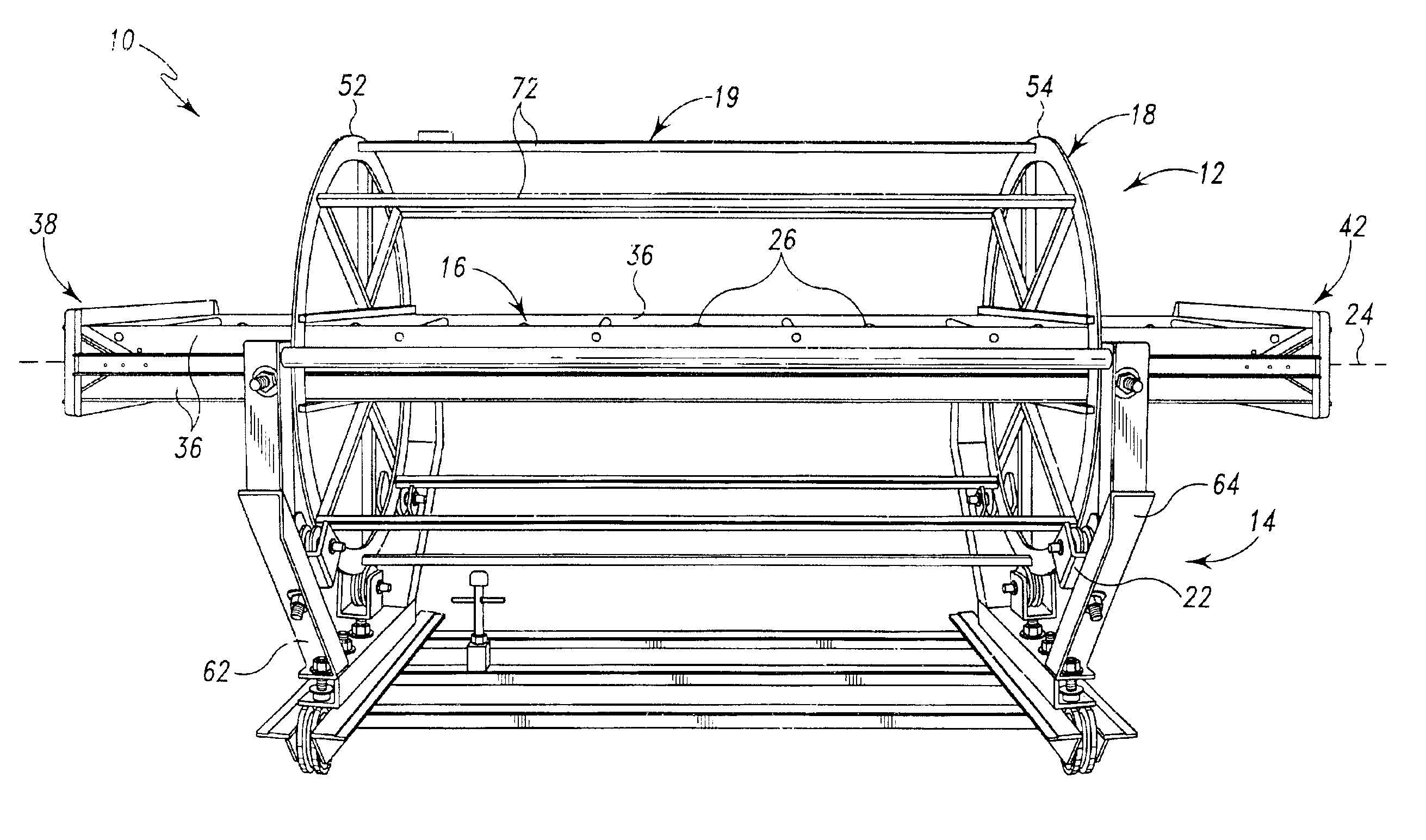
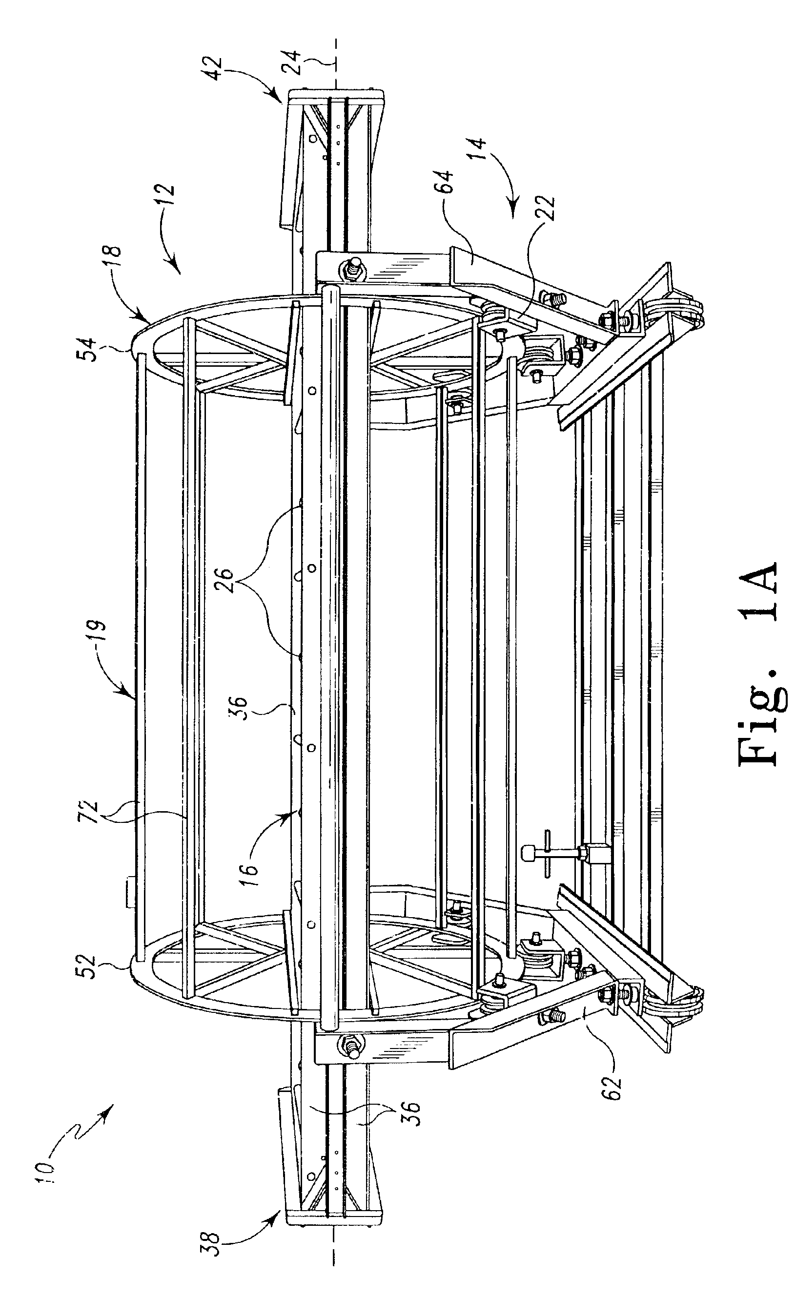
FIG. 1A illustrates a panel turning apparatus according to a presently preferred embodiment of the invention. The apparatus is designated by reference number 10 and generally comprises a rotatable member 12 and a base member 14.

Rotatable member 12 includes a panel carrying portion 16 for carrying a panel to be turned, a supported portion 18 by which the rotatable member is supported for rotation about an axis of rotation 24 thereof and a driving portion 19 by which the rotatable member is rotated. The base member 14 includes a supporting portion 22 which supports the supported portion 18 of the rotatable member.

As best shown in FIGS. 1A and 3, the panel carrying portion 16 of the rotatable member 12 extends along and is aligned with the axis of rotation 24 of the rotatable member. Portion 16 includes a first set of rollers 26 and a second set of rollers 28 which extend parallel to the axis of rotation 24 and which are spaced from one another to define an elongated panel receiving ch...


PUM

PropertyMeasurementUnit
sizesaaaaaaaaaa
sizesaaaaaaaaaa
thicknessaaaaaaaaaa

Abstract

A panel turning apparatus which turns a panel from a first orientation to a second, desired orientation. The apparatus has a rotatable portion rotatable about an axis of rotation thereof, and a base portion which supports the rotatable portion for rotation about the axis of rotation. The rotatable portion has a panel carrying portion aligned with the axis of rotation, a supported portion which supports the rotatable member for rotation and a driving portion by which the rotatable member is rotated to carry a panel carried by the panel carrying portion from the first orientation to the second, desired orientation. The apparatus permits a panel, even a large and heavy panel, to be turned safely and easily by one person.

Description

BACKGROUND OF THE INVENTION1. Field of the InventionThe present invention relates generally to a panel turning apparatus; and, more particularly, to an apparatus for turning a panel from a first orientation to a second, desired orientation.2. Description of the Prior ArtIn the manufacture of panels for various applications, it is often necessary to perform one or more operations on opposite sides of the panels. For example, the Assignee of the present application manufactures panels of solid surfacing material for use in numerous products including counter tops, table tops, wall partition systems and the like; and during the process of manufacturing such panels, it is necessary to sand both sides of the panels. This is typically accomplished by laying a panel on a work table, sanding the upwardly facing side thereof, turning the panel over and then sanding the opposite side.Panels of solid surfacing material, however, are often rather large and heavy. For example, such panels are co...

Claims


Application Information

Patent Timeline
Patent Type & Authority Patents(United States)
IPC IPC(8): B23Q7/02B65G47/248
CPCB23Q7/02B65G47/248Y10T29/53961B65G2201/022
Inventor MAURER, RONALD L.
Owner MAURER RONALD L
Why Eureka
Try Eureka