Aircraft engine mount structure comprising two thrust links with transverse fitting

a technology of engine mount and transverse fitting, which is applied in the direction of aircraft power plant components, transportation and packaging, lighter-than-air aircraft, etc., can solve the problems of high risk of deterioration of engine assembly, no longer being able to disconnect/reconnect, etc., and achieves easy mounting and assembly time saving

Active Publication Date: 2012-12-04
AIRBUS OPERATIONS (SAS)
View PDF14 Cites 16 Cited by
  • Summary
  • Abstract
  • Description
  • Claims
  • Application Information

AI Technical Summary

Benefits of technology

[0017]Therefore, with this configuration particular to the invention, in which each lug extends substantially in transverse direction to the device or slightly at an angle thereto, it becomes easily possible to disconnect / reconnect the aft end of each of the side thrust links e.g. for an engine dismounting / remounting operation. On this account, it is advantageously no longer necessary to dismount / remount the evener bar assembly when carrying out this type of operation.
[0019]Additionally, the easy mounting provided by said arrangement allows savings in terms of assembly time, this also being optimized by the fact that the aft ends of the side thrust links can henceforth be easily interlocked into their associated lug by a mere substantially lateral movement of these links initially connected to the engine via their forward end.
[0023]Preferably, the evener bar is pivoted about a hinge pin which also passes through a bracket for connection to the rigid structure, the thrust load device also comprising an abutment bracket in the shape of a horse-shoe whose central part is crossed by the hinge pin and which is intended to be fixedly joined to the rigid structure, the horse-shoe shaped abutment bracket having an abutment surface located aftwardly relative to the evener bar so that it is able to stop rotation of this evener bar about its hinge pin in both directions.

Problems solved by technology

If the thrust load device is assembled between the engine and the rigid structure, it is no longer possible to disconnect / reconnect the thrust links on the evener bar, such operations nonetheless being desired, for example for later dismounting of the engine.
However, this manner of proceeding requires the positioning of large-size tooling in an area that is little accessible and much congested.
Hence the setting up and handling of this tooling generate high risks of deteriorating the engine assembly, and at all events are synonymous with operating difficulties that are penalizing in terms of assembly time.
By way of indication, these disadvantages are particularly encountered when the tooling is placed in position between the casing of the gas turbine engine and the underside of the evener bar pivot mounted about the above-mentioned hinge pin.

Method used


Image

  • Aircraft engine mount structure comprising two thrust links with transverse fitting
  • Aircraft engine mount structure comprising two thrust links with transverse fitting
  • Aircraft engine mount structure comprising two thrust links with transverse fitting

Examples


Embodiment Construction

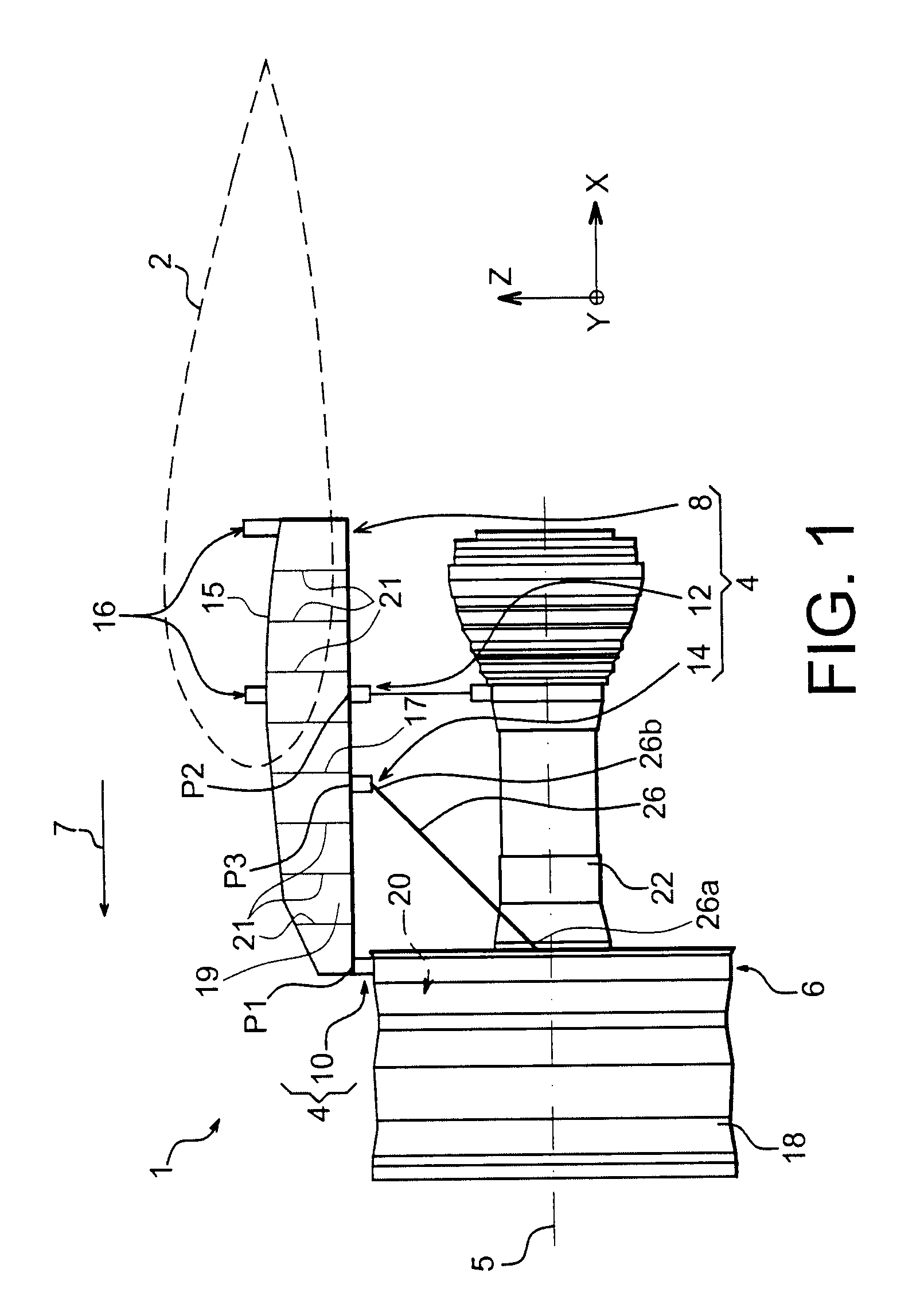
[0036]With reference to FIG. 1, an aircraft engine assembly 1 can be seen, intended to be secured below a wing 2 of this aircraft which is solely illustrated as a dashed outline for reasons of clarity, this assembly 1 comprising a mounting structure 4 according to one preferred embodiment of the present invention, an engine 6 e.g. a turbo-jet engine being mounted below this device 4.

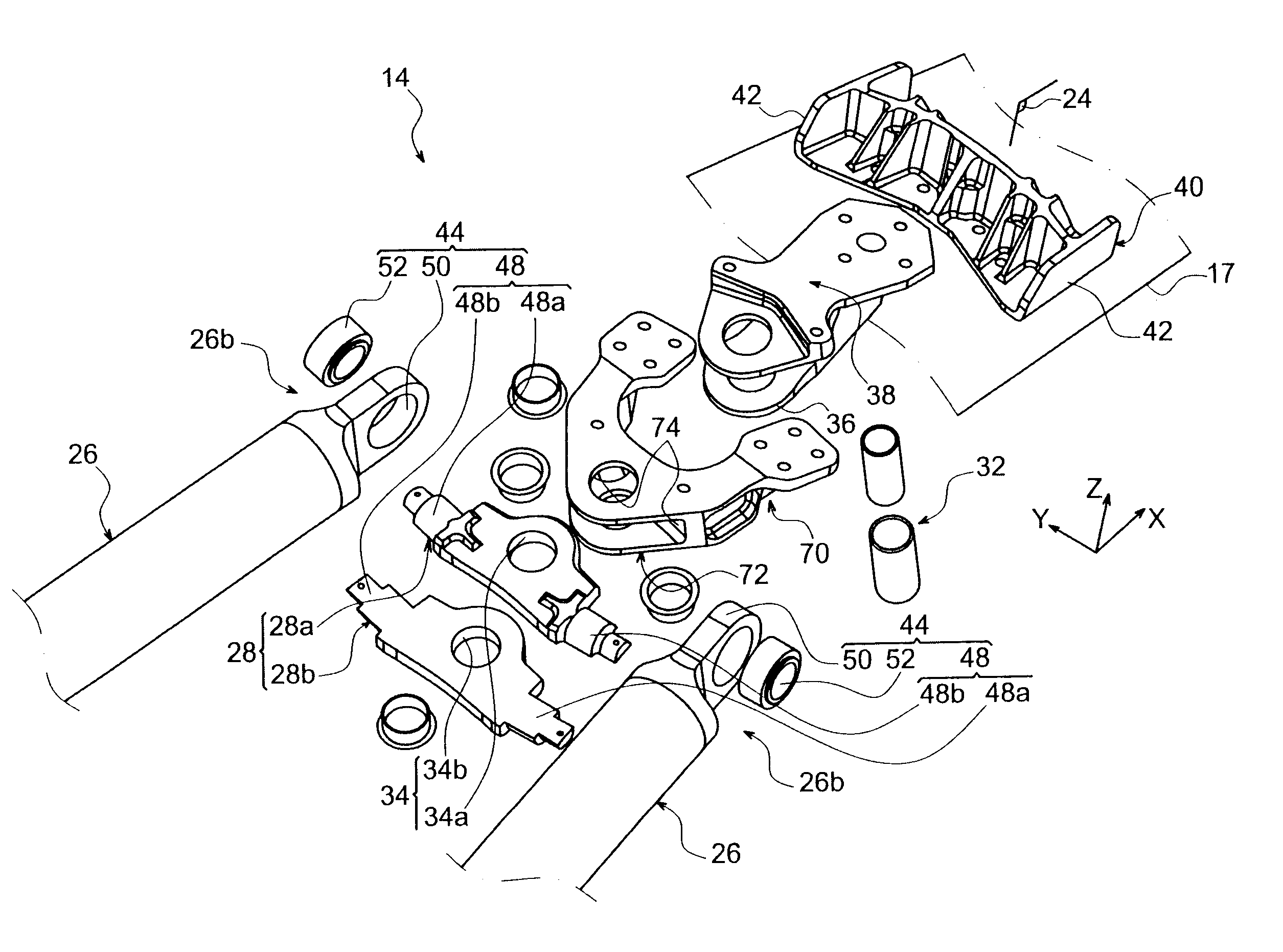
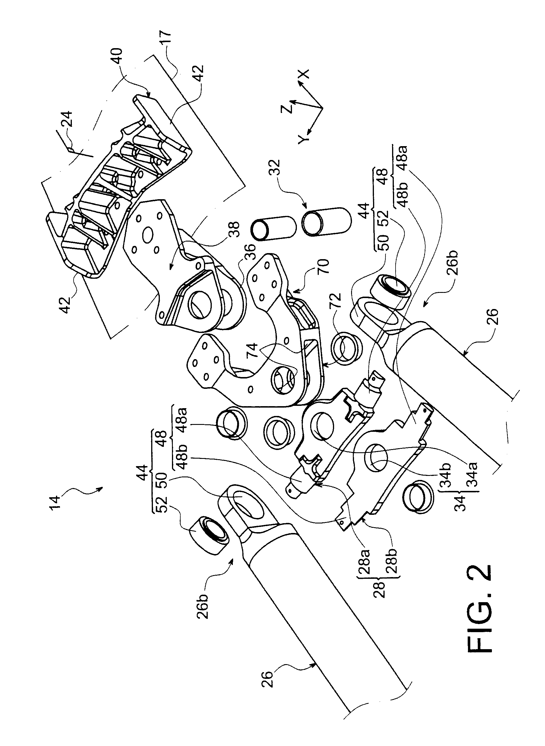
[0037]Globally, the mounting structure 4 comprises a rigid structure 8 carrying means to mount the engine 6, these mounting means having a plurality of engine attachments 10, 12, and a thrust load device 14 to transmit the thrust loads generated by the engine 6.

[0038]By way of indication, it is noted that the assembly 1 is intended to be surrounded by a nacelle (not shown) and the mounting structure 4 comprises another series of attachments 16 for the mounting of this assembly 1 below the wing 2 of the aircraft.

[0039]In the remainder of the following description, X designates the longitudinal direction o...


PUM


Abstract

A mounting structure for an aircraft engine including a rigid structure and a mechanism to mount the engine on the rigid structure. The mounting mechanism includes a thrust load device including two side thrust links each including an aft end mounted on an evener bar of the device, via a mechanical connection. Each connection is formed by a lug provided on the evener bar and passing through an orifice made in the aft end, the lug being arranged so as to extend substantially laterally relative to the mounting structure.

Description

TECHNICAL AREA[0001]The present invention generally relates to an aircraft engine mount intended to be positioned between an aircraft wing and its related engine, and to an engine assembly comprising said mount.[0002]The invention can be used on any type of aircraft equipped with turbo-jet engines or turboprop engines.[0003]This type of mount called “EMS” for Engine Mounting Structure, can be used indifferently to mount an engine below the aircraft wing, to mount this engine above this same wing, or to position this engine on an aft portion of the aircraft fuselage.STATE OF THE PRIOR ART[0004]Said mounting structure is designed to form a connecting interface between a gas turbine engine and an aircraft wing. It permits the loads generated by its associated gas turbine engine to be transmitted to the frame of this aircraft, and also provides a pathway for fuel lines, electrical, hydraulic and air systems between the engine and the aircraft.[0005]To ensure the transmission of loads, t...

Claims


Application Information

Patent Timeline
Patent Type & Authority Patents(United States)
IPC IPC(8): B64D27/00
CPCB64C27/26B64D2027/268B64D27/26
Inventor LEVERT, STEPHANEBEAUFORT, JACQUES
Owner AIRBUS OPERATIONS (SAS)
Why Eureka
Try Eureka