Drive torque distribution apparatus

a technology of torque distribution and torque distribution, which is applied in the direction of differential gearings, belts/chains/gearrings, differential gearings, etc., can solve the problems of loss and complex structure of torque distribution adjustmen

Active Publication Date: 2014-10-23
TOYOTA CENT RES & DEV LAB INC
View PDF9 Cites 15 Cited by
  • Summary
  • Abstract
  • Description
  • Claims
  • Application Information

AI Technical Summary

Benefits of technology

[0008]According to one aspect of the present invention, there is provided a drive torque distribution apparatus comprising: a differential device that permits a rotational difference between a first drive shaft and a second shaft; and a torque distribution adjusting device that adjusts a torque distribution between the first drive shaft and the second drive shaft, wherein the torque distribution adjusting device includes a rotary electric machine that can generate a torque between a first rotor and a second rotor rotatable relative to each other, the torque distribution adjusting device transmits rotation of the first and second rotors or rotation corresponding to a rotational difference between the first rotor and the second rotor to the differential device, the first rotor and the second rotor rotate at equal rotational speeds when the first drive shaft and the second drive shaft rotate at equal rotational speeds, a torque is generated between the first rotor and the second rotor to generate a rotational difference between the first rotor and the second rotor and to consequently generate a rotational difference between the first drive shaft and the second shaft, and the torque distribution between the first drive shaft and the second drive shaft is adjusted according to the torque generated between the first rotor and the second rotor.
[0009]According to another aspect of the present invention, preferably, the torque distribution adjusting device further comprises a rotation transmitting device that transmits the rotation corresponding to the rotational difference between the first rotor and the second rotor to the first drive shaft or the second drive shaft.
[0010]According to another aspect of the present invention, preferably, the rotation transmitting device amplifies and outputs the torque generated between the first rotor and the second rotor.
[0011]According to another aspect of the present invention, preferably, the differential device comprises: a first differential rotation element that rotates with the first drive shaft; a second differential rotation element that rotates with the second drive shaft; a third differential rotation element that transmits rotation between the first and second differential rotation elements, and a fourth differential rotation element that rotatably supports the third differential rotation element and that causes, with rotation thereof, the third differential rotation element to circle around a rotational axis of the first differential rotation element, wherein the rotational difference between the first drive shaft and the second drive shaft is permitted by rotation of the third differential rotation element, and the rotation transmitting device comprises: a first transmitting rotation e

Problems solved by technology

However, in order to realize the spinning of the pinion gear of the differential device by the rotational driving of the rotor, it is necessary to use three planetary gear mechanisms, resulting in complexity of the structure for adjusting the torque distribution.
However, in this ca

Method used


Image

  • Drive torque distribution apparatus
  • Drive torque distribution apparatus
  • Drive torque distribution apparatus

Examples


second preferred embodiment

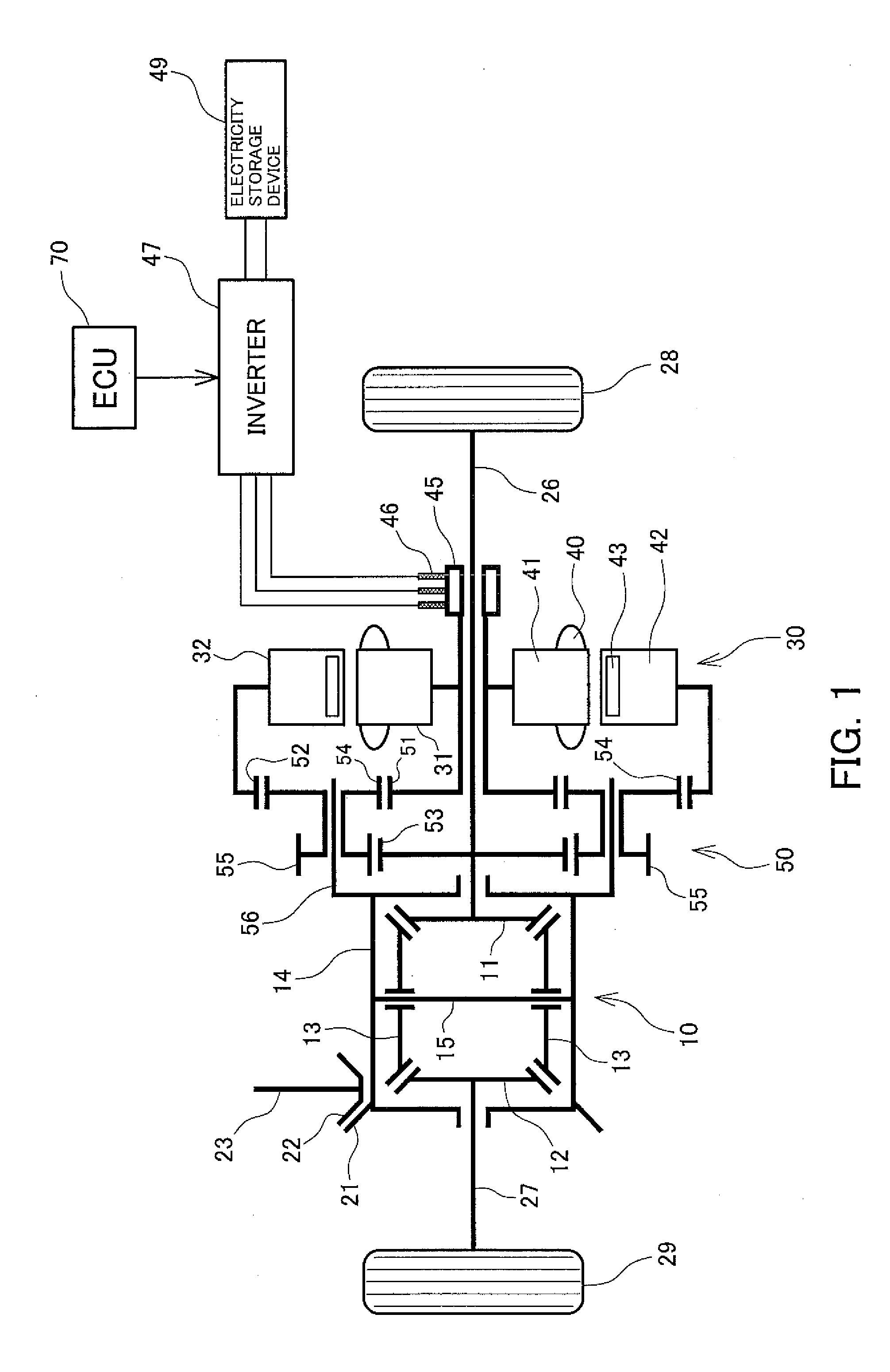
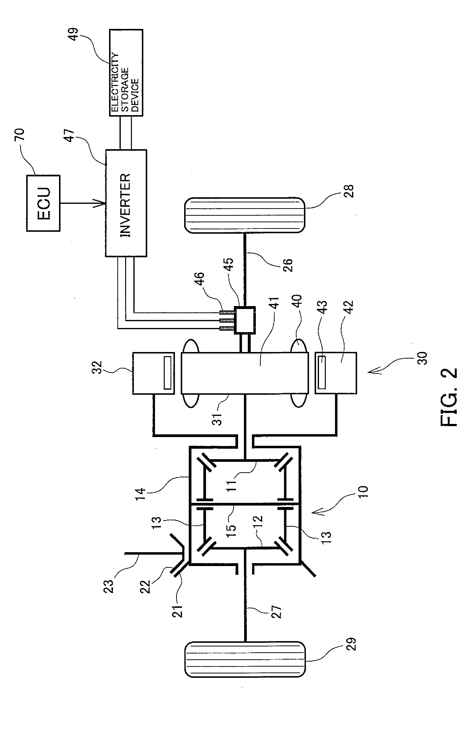
[0047]FIG. 2 is a diagram schematically showing a drive torque distribution device according to a second preferred embodiment of the present invention. In the following description of the second preferred embodiment, structures similar to or corresponding to the structures of the first preferred embodiment are assigned the same reference numerals, and structures that are not specifically described are similar to those of the first preferred embodiment.

[0048]In the present embodiment, the first rotor 31 and the slip ring 45 mechanically engage the right drive shaft 26 and integrally rotate with the right side gear 11 and the right drive shaft 26 at equal rotational speeds. The second rotor is mechanically linked to the rotation case 14, and integrally rotates with the rotation case 14 at an equal rotational speed. In the example configuration shown in FIG. 2, the first rotor 31 and the second rotor 32 oppose in the radial direction orthogonal to the rotor rotational axis, the second ...

third preferred embodiment

[0059]FIG. 3 is a diagram schematically showing a structure of a drive torque distribution apparatus according to a third preferred embodiment of the present invention. In the following description of the third preferred embodiment, structures similar to or corresponding to the structures of the first and second preferred embodiments are assigned the same reference numerals, and structures that are not specifically described are similar to those of the first and second preferred embodiments.

[0060]In the present embodiment, the differential device 10 is formed from a differential gear device comprising a pair of side gears 11 and 12 acting as first and second differential rotation elements, a plurality of pinion gears 13-1 and 13-2 acting as a third differential rotation element, and a rotation case 14 acting as a fourth differential rotation element. The side gears 11 and 12 and the pinion gears 13-1 and 13-2 are formed with outer gears, the pinion gears 13-1 engage the right side g...

fourth preferred embodiment

[0071]FIG. 4 is a diagram schematically showing a drive torque distribution device according to a fourth preferred embodiment of the present invention. In the following description of the fourth preferred embodiment, structures identical to or corresponding to those of the first through third preferred embodiments are assigned the same reference numerals, and structures that are not described are similar to those in the first through third preferred embodiments.

[0072]In the present embodiment, compared to the first preferred embodiment, the rotary electric machine 30 further comprises a stator 33 which is placed opposing the second rotor with a predetermined gap therebetween. The stator 33 comprises a stator core 34 and a stator winding 35 of a plurality of phases (for example, three phases) placed on the stator core 34 along a circumferential direction thereof. By an AC current of a plurality of phases (for example, three phases) flowing in the stator winding 35 of the plurality of...


PUM


Abstract

When a first drive shaft and a second drive shaft rotate at equal rotational speeds, a first rotor and a second rotor rotate at equal rotational speeds. On the other hand, a rotational difference is generated between the first drive shaft and the second shaft by generating a torque between the first rotor and the second rotor and consequently, a rotational difference between the first rotor and the second rotor, so that a torque distribution between the first drive shaft and the second drive shaft is adjusted according to the torque generated between the first rotor and the second rotor. With this process, the torque distribution between the first drive shaft and the second drive shaft is adjusted without complicating the structure, and a loss when the first drive shaft and the second drive shaft rotate at equal rotational speeds is reduced.

Description

PRIORITY INFORMATION[0001]This application claims priority to Japanese Patent Application No. 2013-086252, filed on Apr. 17, 2013, which is incorporated herein by reference in its entirety.BACKGROUND[0002]1. Technical Field[0003]The present invention relates to a drive torque distribution apparatus which adjusts a torque distribution between a first drive shaft and a second drive shaft.[0004]2. Related Art[0005]International Publication No. 2011 / 76542 discloses a technique related to a drive torque distribution apparatus of this type. The drive torque distribution apparatus of International Publication No. 2011 / 76542 comprises a differential device, first, second, and third planetary gear mechanisms, and a motor. The motor has a stator and a rotor, and the rotor is linked to a sun gear of the first planetary gear mechanism. Carriers of the first and second planetary gear mechanisms are linked, and rotation of the sun gear of the second planetary gear mechanism is fixed. A ring gear ...

Claims


Application Information

Patent Timeline
IPC IPC(8): F16H48/06
CPCF16H48/06F16H48/36F16H48/34F16H2048/343F16H2048/364
Inventor WATANABE, TAKAO
Owner TOYOTA CENT RES & DEV LAB INC
Why Eureka
Try Eureka