
Torque limiter, display screen turning apparatus comprising torque limiter and television set including torque limiter

a technology of display screen turning apparatus and torque limiter, which is applied in the direction of couplings, slip couplings, television systems, etc., can solve the problems of inability to transmit bidirectional rotation, and disadvantageous so as to suppress the increase in the number of components

Inactive Publication Date: 2012-02-21
FUNAI ELECTRIC CO LTD
View PDF23 Cites 0 Cited by
  • Summary
  • Abstract
  • Description
  • Claims
  • Application Information

AI Technical Summary

Benefits of technology

The present invention provides a torque limiter that can transmit bidirectional rotation while suppressing increase in the number of components. The torque limiter includes a first rotating member and a second rotating member with a spring member in between them. The first rotating member has a spring storage portion enclosed with a plurality of fragment portions. The second rotating member has a fit portion fitted with the outer peripheral surfaces of the fragment portions of the first rotating member. The spring member press-fits into the spring storage portion, inhibiting slipping out of the spring member. The torque limiter is designed to transmit the driving torque in response to the pressure contact force applied by the spring member. The plurality of fragment portions of the first rotating member and the fit portion of the second rotating member are in surface contact with each other, preventing detachment of the second rotating member from the first rotating member. The fixed shaft portion and the second shaft receiving portion are integrally provided with the first and second engaging portions, reducing the number of components.

Problems solved by technology

Therefore, bidirectional rotation cannot be transmitted.
Therefore, the number of components is disadvantageously increased.

Method used


Image

  • Torque limiter, display screen turning apparatus comprising torque limiter and television set including torque limiter
  • Torque limiter, display screen turning apparatus comprising torque limiter and television set including torque limiter
  • Torque limiter, display screen turning apparatus comprising torque limiter and television set including torque limiter

Examples


Embodiment Construction

[0057]An embodiment of the present invention is now described with reference to the drawings.

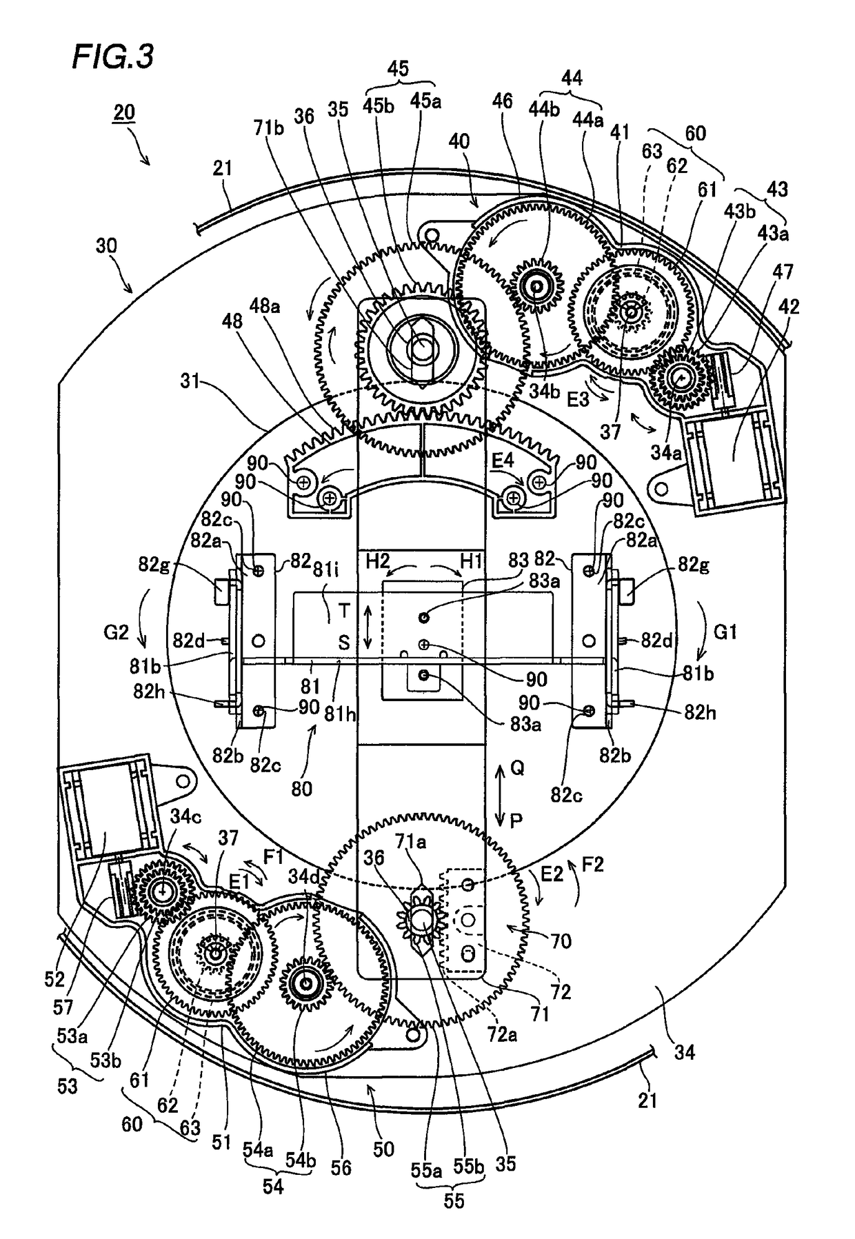
[0058]First, the structures of a torque limiter and a display screen turning apparatus provided with the torque limiter according to the embodiment of the present invention are described with reference to FIGS. 1 to 17. According to this embodiment, the present invention is applied to the display screen turning apparatus for a liquid crystal display employed as an exemplary television set.

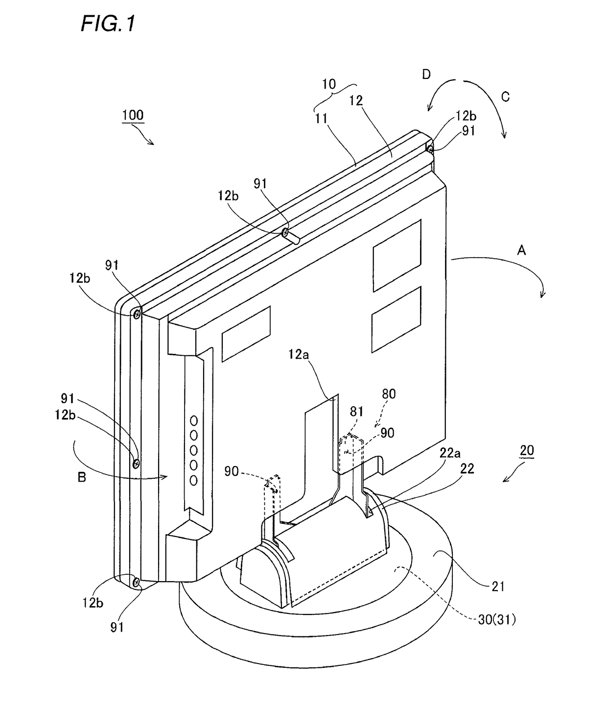
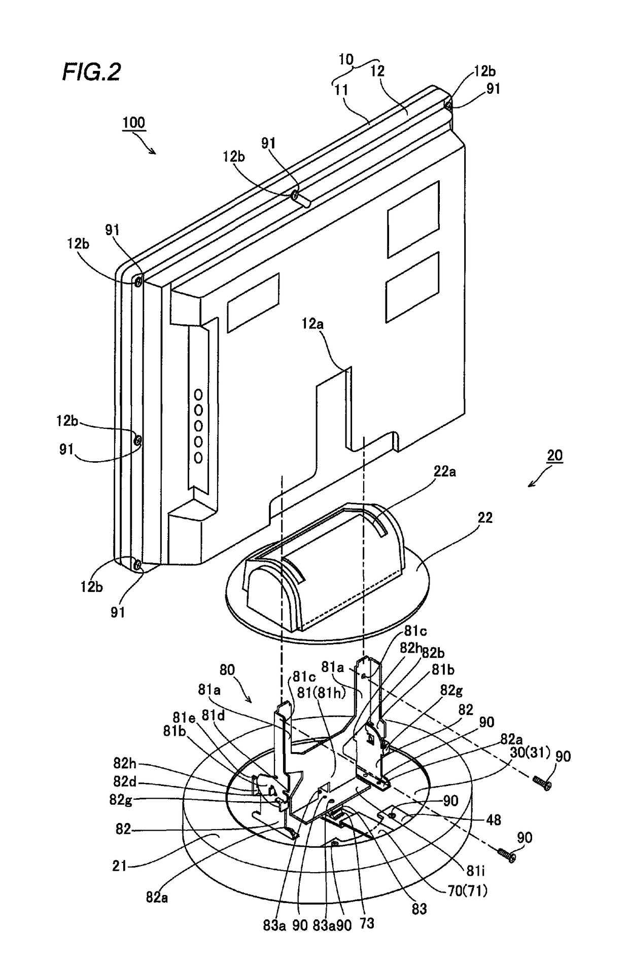
[0059]As shown in FIG. 1, a display screen turning apparatus 20 according to the embodiment of the present invention is so provided as to enable a display body 10 of a liquid crystal display 100 supported by a display screen support mechanism 80 to turn in a horizontal direction (along arrow A or B) by a prescribed angle in a horizontal plane and to be inclined in the anteroposterior direction (along arrow C or D) by a prescribed angle with respect to a vertical plane. The display body 10 is an example of t...


PUM


Abstract

This torque limiter includes a first rotating member integrally provided with a plurality of fragment portions in a concentric manner and having a spring storage portion enclosed with the plurality of fragment portions, a second rotating member having a lid portion arranged to cover the spring storage portion of the first rotating member and a fit portion fitted with the outer peripheral surfaces of the plurality of fragment portions of the first rotating member and a spring member press-fitted into the spring storage portion enclosed with the inner peripheral surfaces of the plurality of fragment portions of the first rotating member thereby bringing the plurality of fragment portions into pressure contact with the fit portion of the second rotating member, for transmitting driving torque in response to pressure contact force applied by the spring member.

Description

BACKGROUND OF THE INVENTION[0001]1. Field of the Invention[0002]The present invention relates to a torque limiter, a display screen turning apparatus comprising a torque limiter and a television set including a torque limiter.[0003]2. Description of the Background Art[0004]A torque limiter having a spring member is known in general, as disclosed in each of Japanese Utility Model Laying-Open No. 5-15140 (1993), Japanese Patent Laying-Open No. 6-180899 (1994) and Japanese Patent Laying-Open No. 6-176444 (1994), for example.[0005]The aforementioned Japanese Utility Model Laying-Open No. 5-15140 discloses a reel driving apparatus comprising a lower coupling gear, provided with a first boss, receiving power transmitted thereto, an upper coupling gear provided with a second boss into which an upper portion of the first boss is inserted and a clutch spring (spring member) inserted into the first and second bosses and arranged to be held between the lower and upper coupling gears. The reel ...

Claims


Application Information

Patent Timeline
Patent Type & Authority Patents(United States)
IPC IPC(8): H04N5/64
CPCF16D7/021F16D43/211F16M11/08F16M11/10F16M11/18F16M11/2014F16M2200/044F16M2200/08
Inventor SHIMIZU, DAISUKE
Owner FUNAI ELECTRIC CO LTD
Learn More