Voltage detection device, voltage detection method, abnormality determination device, abnormality determination method, and battery pack system

a voltage detection and abnormality detection technology, applied in measurement devices, electrical testing, instruments, etc., can solve the problems of circuit scale and manufacturing cost increase, and achieve the effect of suppressing the increase in the number of components of the circui

Active Publication Date: 2019-07-16
FUJITSU GENERAL LTD
View PDF8 Cites 0 Cited by
  • Summary
  • Abstract
  • Description
  • Claims
  • Application Information

AI Technical Summary

Benefits of technology

[0008]However, according to the devices of the related art, the Zener diode or the plurality of voltage detection circuits is required so as to detect the abnormality, which increases the number of components. When the number of components increases, a circuit scale and the manufacturing cost also increase.
[0009]In view of above, at least one embodiment of the present invention provides an art capable of suppressing increase in the number of components.
[0011]According to the at least one embodiment of the present invention, it is possible to suppress the increase in the number of components of the circuit.

Problems solved by technology

When the number of components increases, a circuit scale and the manufacturing cost also increase.

Method used


Image

  • Voltage detection device, voltage detection method, abnormality determination device, abnormality determination method, and battery pack system
  • Voltage detection device, voltage detection method, abnormality determination device, abnormality determination method, and battery pack system
  • Voltage detection device, voltage detection method, abnormality determination device, abnormality determination method, and battery pack system

Examples


Embodiment Construction

[0038]Hereinafter, illustrative embodiments of the voltage detection device, the voltage detection method and the battery pack system of the disclosure will be described in detail with reference to the accompanying drawings. In the meantime, it should be noted that the disclosure is not limited to the illustrative embodiments.

A. First Illustrative Embodiment

A1. Configuration of Battery Pack System

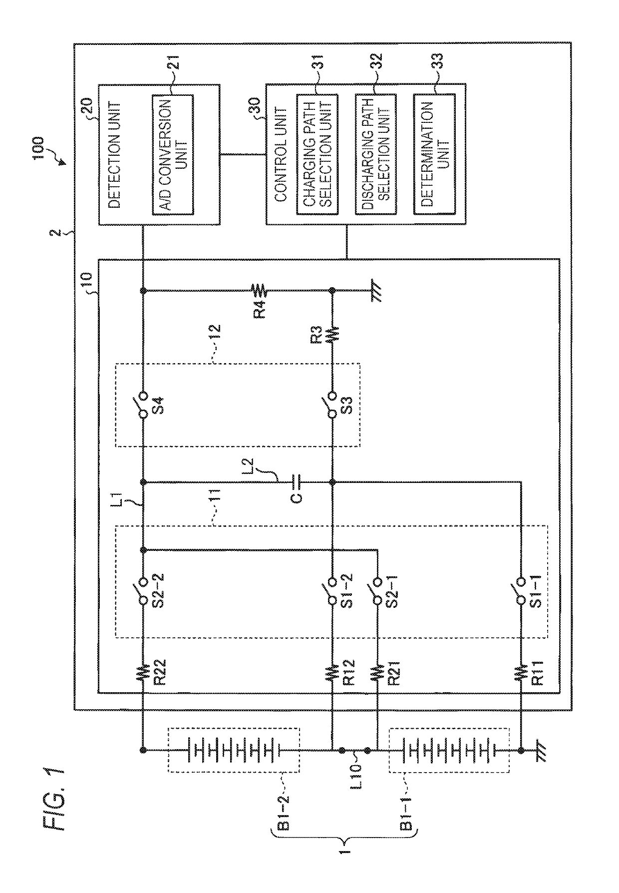
[0039]FIG. 1 depicts a configuration example of a battery pack system 100 according to a first illustrative embodiment. The battery pack system 100 shown in FIG. 1 has a battery pack 1, and a monitoring device 2 configured to operate as a voltage detection device configured to detect a voltage of the battery pack 1.

[0040]The battery pack 1 has a plurality of battery stacks B1-n (n=1 to N, N: natural number; hereinafter, also referred to as the battery stack B1) connected in series via a connection member L10-m (m=1 to N−1, N: natural number; hereinafter, also referred to as the connection m...


PUM


Abstract

A voltage detection device includes battery stacks, and a connection member configured to electrically connect the battery stacks. The voltage detection device includes: a capacitor connected to each battery stack in parallel; switches, each of which having one end connected to a terminal of each battery stack and the other end connected to the capacitor; a detection unit configured to detect a voltage of the capacitor, and a control unit configured to control the switches, in which the control unit comprises: a discharging path selection unit that selects a discharging path comprising the connection member and the capacitor when discharging the capacitor, and a determination unit configured to determine whether an abnormality has occurred in the battery pack or at least one of the switches, in correspondence to at least one of a voltage of the capacitor after charging and a voltage of the capacitor after discharging.

Description

CROSS-REFERENCE TO RELATED APPLICATIONS[0001]This application is based on and claims priority under 35 USC 119 from Japanese Patent Application No. 2015-039204 filed on Feb. 27, 2015 and Japanese Patent Application No. 2015-039205 filed on Feb. 27, 2015, the entire contents of which are incorporated herein by reference.BACKGROUND[0002]1. Technical Field[0003]The present invention relates to a voltage detection device, a voltage detection method, an abnormality determination device, an abnormality determination method and a battery pack system.[0004]2. Related Art[0005]A battery pack in which battery stacks, each of which has a plurality of battery cells connected in series, are connected in series has been used as a power supply of an electric vehicle and a hybrid electric vehicle, for example. The battery pack is connected with a monitoring device configured to monitor the battery pack. The monitoring device is configured to operate as a voltage detection device configured to detec...

Claims


Application Information

Patent Timeline
Patent Type & Authority Patents(United States)
IPC IPC(8): G01R31/396G01R31/327G01R31/3835
CPCG01R31/396G01R31/3277G01R31/3835
Inventor IWANAGA, TAKEHITOIZUTANI, ATSUSHIKONDO, AKIHITOOGAWA, KAZUYA
Owner FUJITSU GENERAL LTD
Why Eureka
Try Eureka