Image Generating Apparatus

Inactive Publication Date: 2008-08-14
FUNAI ELECTRIC CO LTD
View PDF4 Cites 0 Cited by
  • Summary
  • Abstract
  • Description
  • Claims
  • Application Information

AI Technical Summary

Benefits of technology

[0015]The present invention has been proposed in order to solve the aforementioned problems, and an object of the present invention is to provide

Problems solved by technology

In the thermal transfer printer (image generating apparatus) described in the aforementioned Japanese Patent No. 3272627, however, rotation of the thermal head is regulated by the engagement between the control bosses of the thermal head and the notches of the driving gear mounting portions, whereby the engagement between the control bosses and the notches may conceivably be incomplete if the accuracy of the rotation angle of the cam gear is insufficient.
In this case, constant pressing force cannot be obtained for the thermal head (print head).
In the thermal transfer printer described in the aforementioned Japanese Patent No. 3272627, further, the driving gear is provided independently of the shaft member, whereby the number of components of the thermal transfer printer is disadvantageously increased.
If such vibration of the cam gear is propagated from the cam gear to the head separating cam lever, the head separating cam lever cannot apply constant pressing force to the print head due to jolting resulting from the vibration.
In the ink jet

Method used


Image

  • Image Generating Apparatus
  • Image Generating Apparatus
  • Image Generating Apparatus

Examples


first embodiment

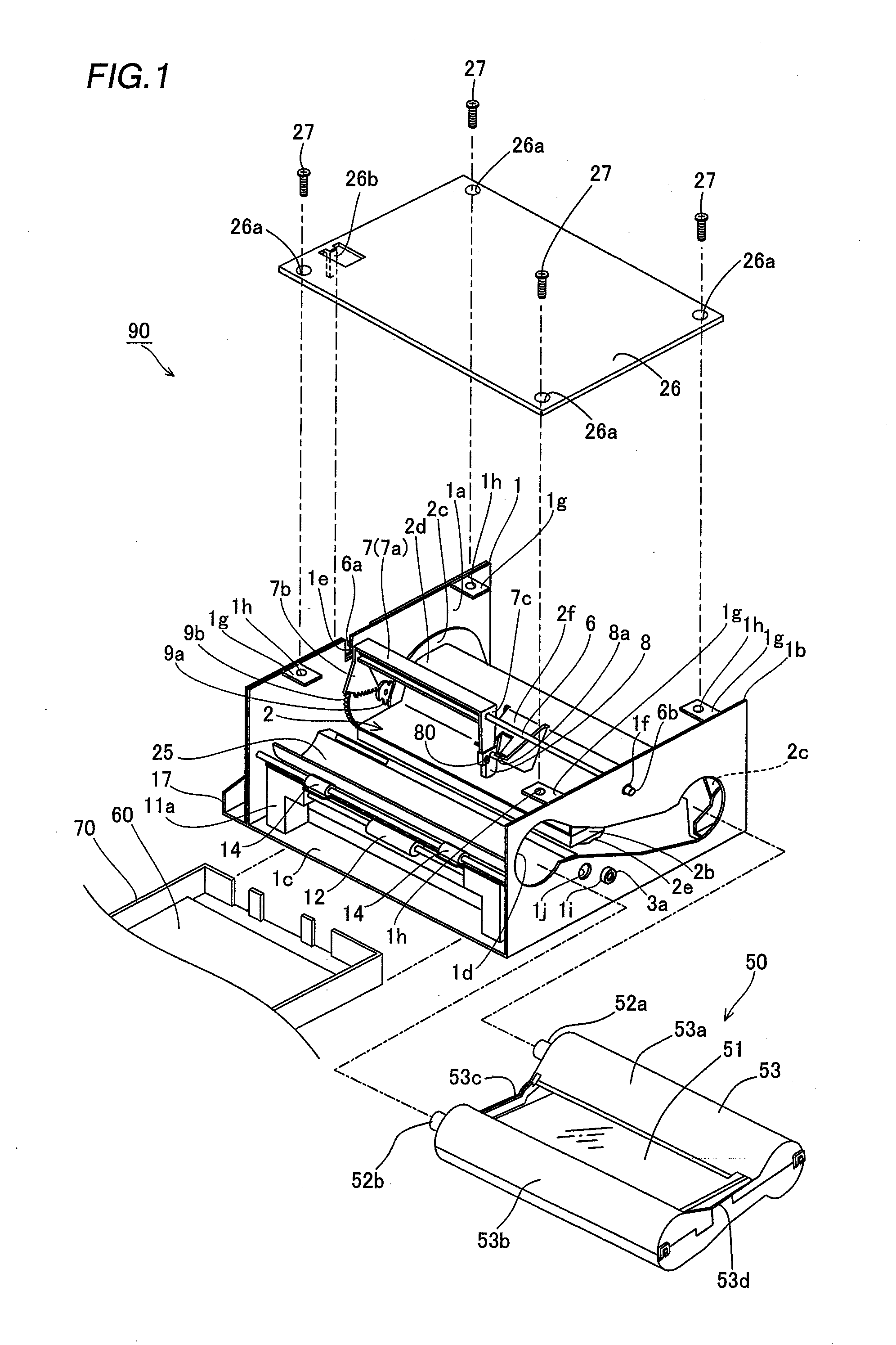
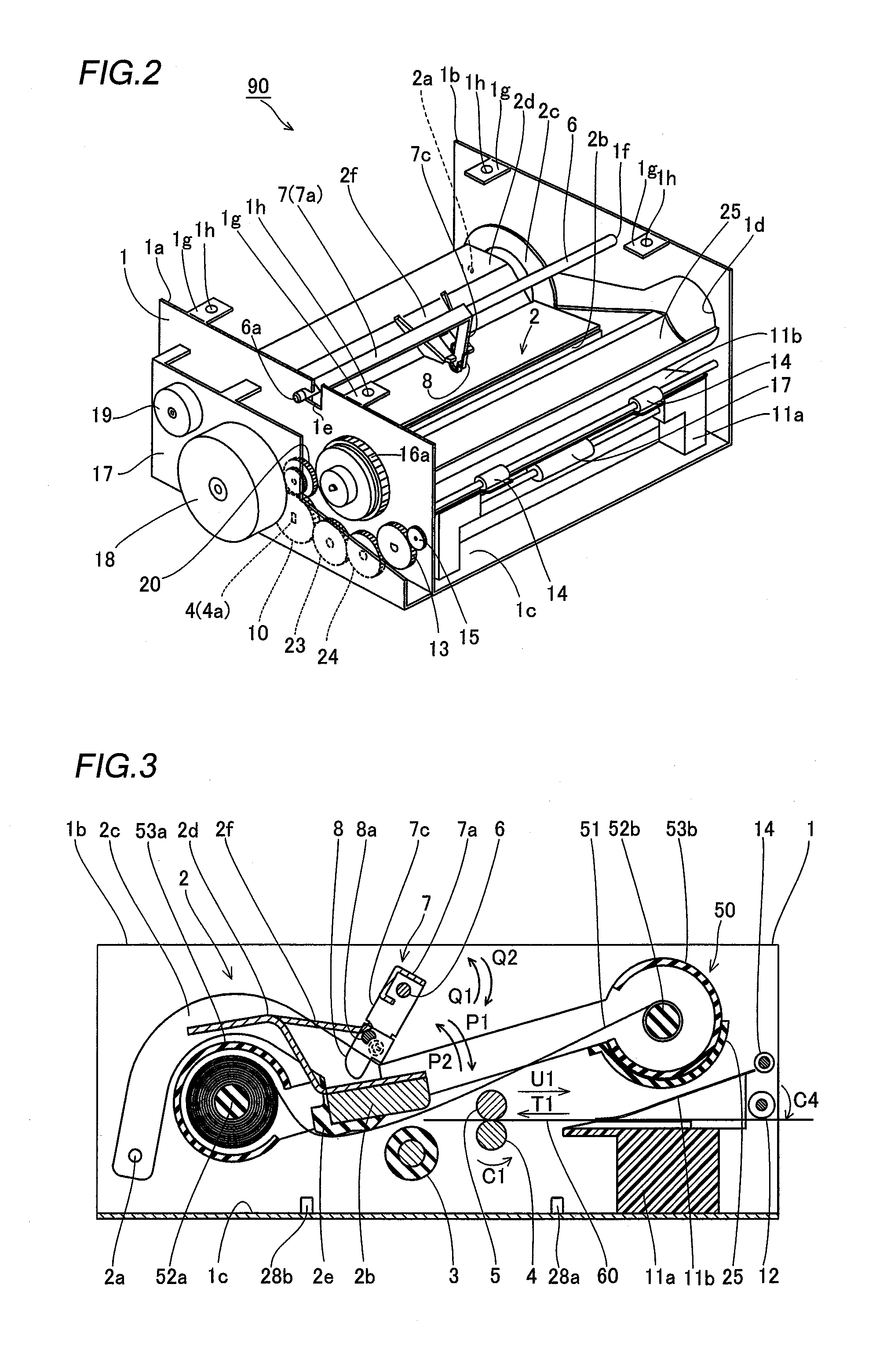
[0059]First, the structure of a sublimatic printer according to a first embodiment of the present invention is described with reference to FIGS. 1 to 11. According to the first embodiment, the present invention is applied to the sublimatic printer employed as an exemplary image generating apparatus.

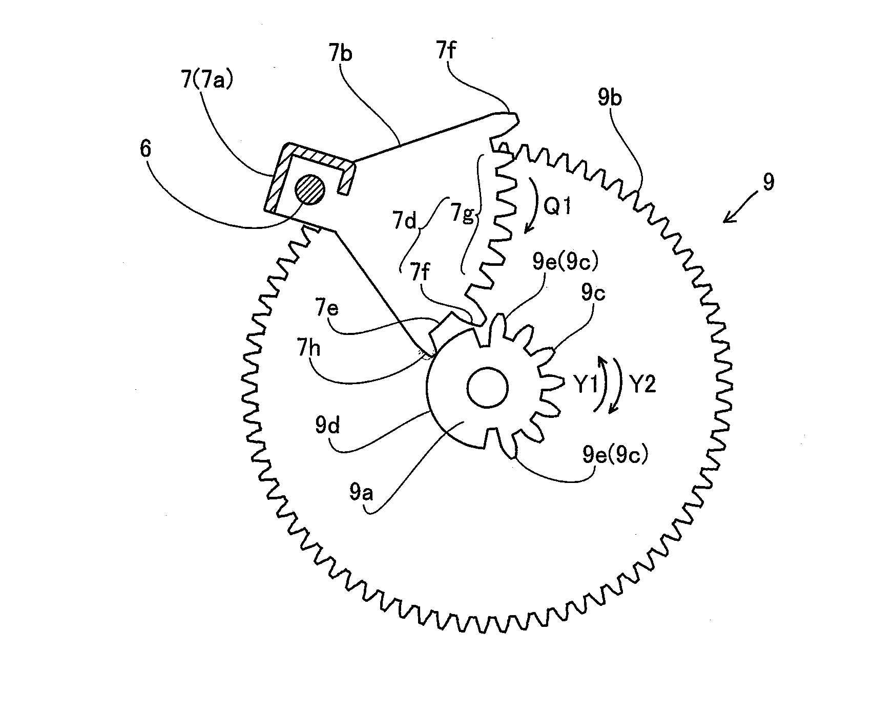
[0060]As shown in FIG. 1, a printer body 90 of the sublimatic printer according to the first embodiment of the present invention comprises a chassis 1 of metal (sheet metal), a print head 2 for printing images, a platen roller 3 (see FIG. 3) opposed to the print head 2, a feed roller 4 (see FIG. 3) of metal, a press roller 5 (see FIG. 3) of metal pressing the feed roller 4 with prescribed pressing force, a support rod 6 of metal, a print head rotating member 7 of sheet metal, a head portion pressing member 8 of resin for pressing the print head 2, a driving gear 9 of resin and a feed roller gear 10 (see FIG. 4). The printer body 90 of the sublimatic printer further comprises a lower paper...

second embodiment

[0104]The structure of a printer body 100 of a sublimatic printer according to a second embodiment of the present invention is now described with reference to FIGS. 17 to 25. In the printer body 100 of the sublimatic printer according to the second embodiment, a print head rotating member 101 is made of not sheet metal but resin, dissimilarly to the printer body 90 of the sublimatic printer according to the aforementioned first embodiment.

[0105]The printer body 100 of the sublimatic printer according to the second embodiment comprises the print head rotating member 101 of resin pressing a print head 2, as shown in FIG. 17.

[0106]The print head 2 includes a heat radiating member 102 of aluminum for radiating heat from a head portion 2b, as shown in FIG. 17.

[0107]According to the second embodiment, the print head rotating member 101 has a sectorial driven gear portion 101b and a pressing portion 101c integrally provided on both longitudinal ends of a body portion 101a respectively, as ...


PUM


Abstract

In this image generating apparatus, a driving gear portion is so formed that the diameter of the outer peripheral surface of a first toothless portion is smaller than the tip diameter of a first toothed portion, and so arranged that the first toothless portion thereof slides on a second toothed portion of a driven gear portion of a print head rotating member in the vicinity of a position where a print head presses a platen roller with a pressing portion.

Description

BACKGROUND OF THE INVENTION[0001]1. Field of the Invention[0002]The present invention relates to an image generating apparatus comprising a print head printing images while pressing a platen roller with prescribed pressing force.[0003]2. Description of the Background Art[0004]An image generating apparatus comprising a print head printing images while pressing a platen roller with prescribed pressing force and the like is known in general, as disclosed in each of Japanese Patent No. 3272627 and Japanese Patent Laying-Open Nos. 7-269589 (1995), 8-62688 (1996), 2003-156066 and 7-251554 (1995), for example.[0005]The aforementioned Japanese Patent No. 3272627 discloses a thermal transfer printer (image generating apparatus) comprising a cam gear, a driving gear, a shaft member (rotational member) having driving gear mounting portions and synchronous cam portions integrally provided on both ends of a rotating shaft respectively and a thermal head (print head) supported by an arm through a...

Claims


Application Information

Patent Timeline
IPC IPC(8): B41J25/304
CPCB41J25/312B41J25/304
Inventor SAWAI, KUNIONAITO, TAKAHIRO
Owner FUNAI ELECTRIC CO LTD
Why Eureka
Try Eureka