Structure for mounting indicator unit on electronic apparatus

a technology for mounting structures and indicators, applied in the direction of electrical apparatus construction details, television systems, printed circuits, etc., can solve the problems of disadvantageous etc., to achieve the effect of suppressing the increase in the number of components

Inactive Publication Date: 2011-10-25
FUNAI ELECTRIC CO LTD
View PDF13 Cites 1 Cited by
  • Summary
  • Abstract
  • Description
  • Claims
  • Application Information

AI Technical Summary

Benefits of technology

[0011]The present invention has been proposed in order to solve the aforementioned problems, and an object of the present invention is to provide a structure for mounting an indicator unit on an electronic apparatus capable of correctly keeping the positional relation between a light source portion of a wiring board and a lens member while suppressing increase in the number of components, with no requirement for dedicated screw members for fixing the wiring board.

Problems solved by technology

Therefore, the number of components is disadvantageously increased.
When the wiring board and the lens member are separately fixed in this manner, it is disadvantageously difficult to correctly keep the positional relation between a light source portion mounted on the wiring board and the lens member.

Method used


Image

  • Structure for mounting indicator unit on electronic apparatus
  • Structure for mounting indicator unit on electronic apparatus
  • Structure for mounting indicator unit on electronic apparatus

Examples


Embodiment Construction

[0047]An embodiment of the present invention is now described with reference to the drawings.

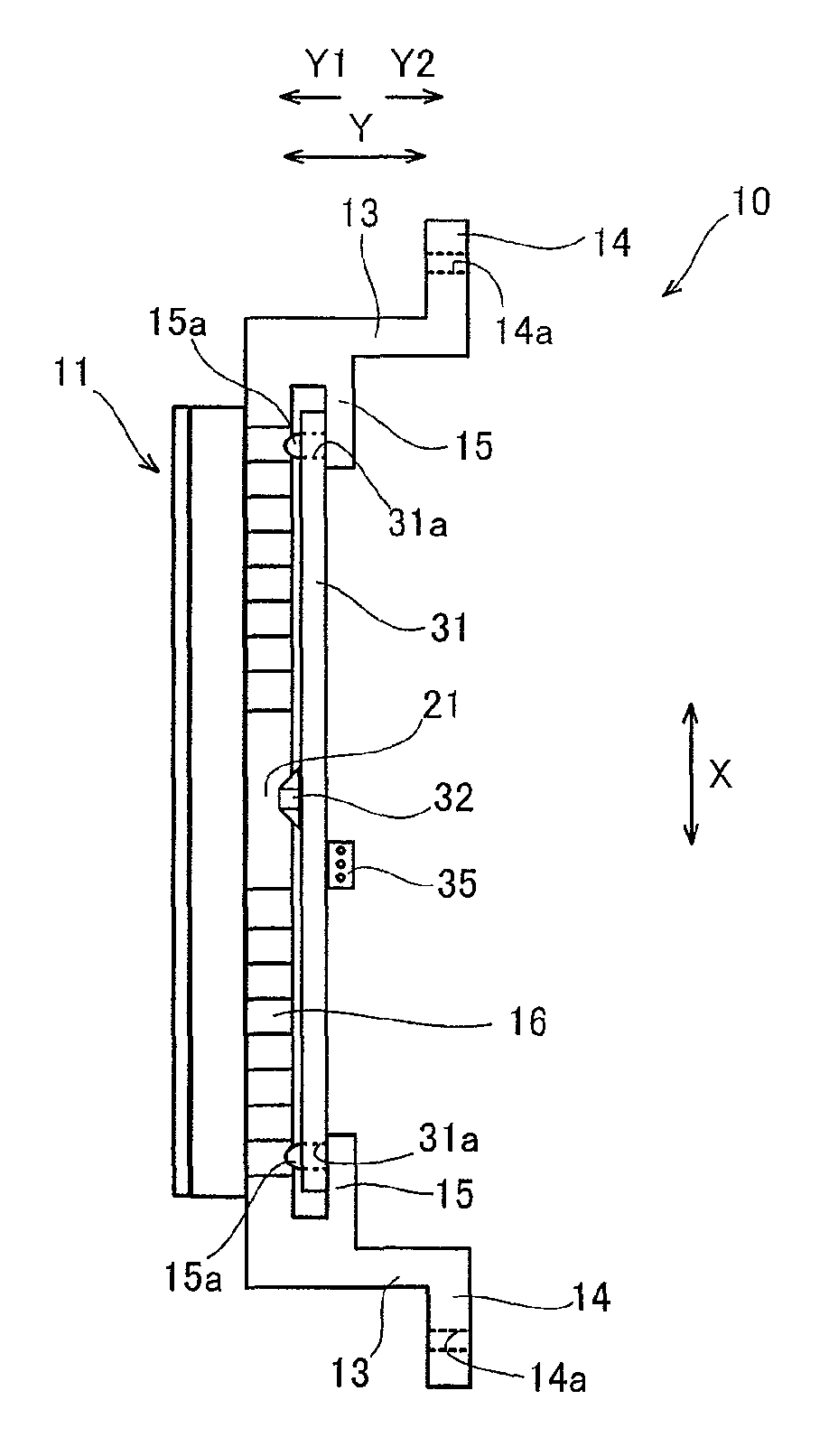
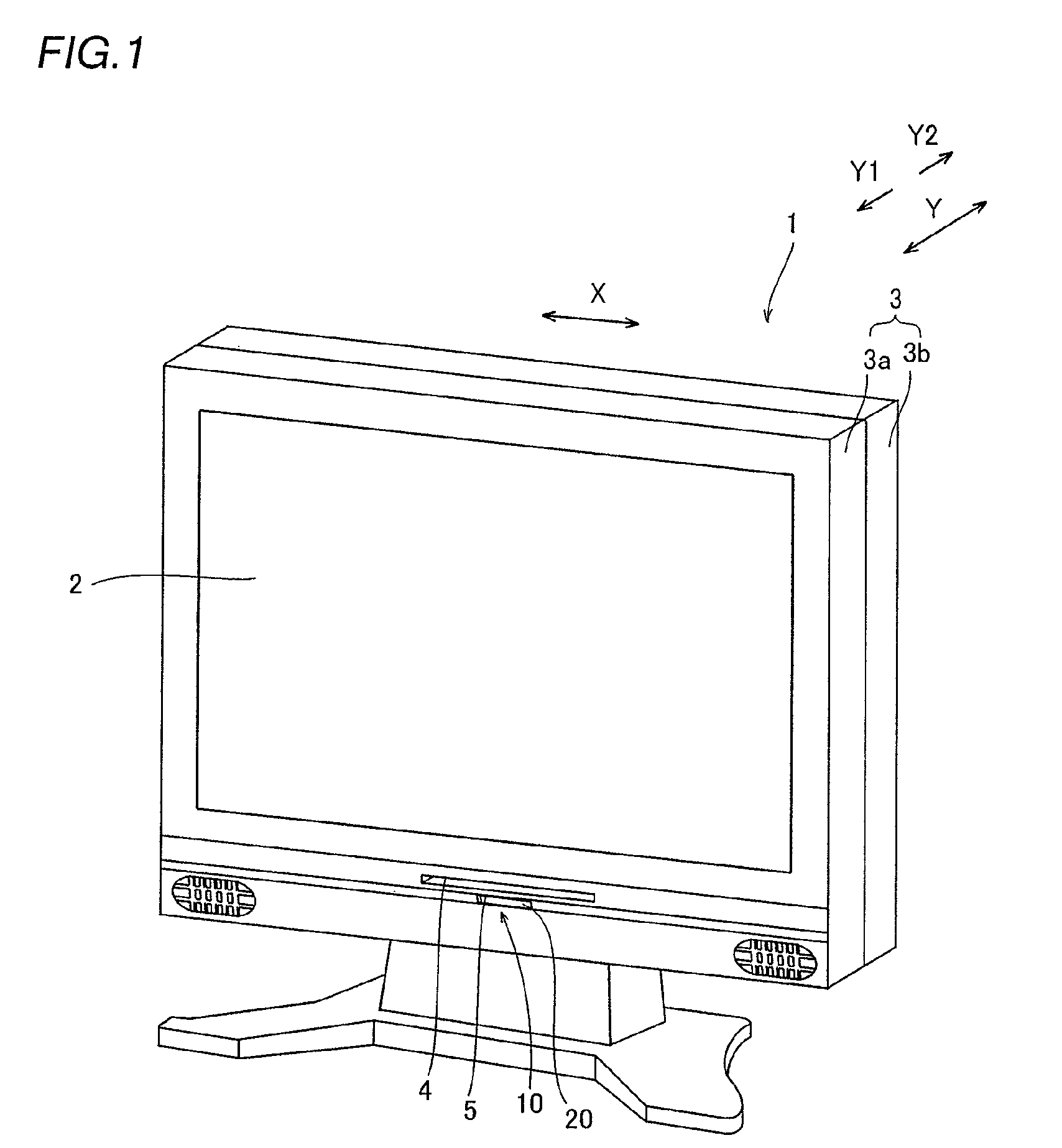
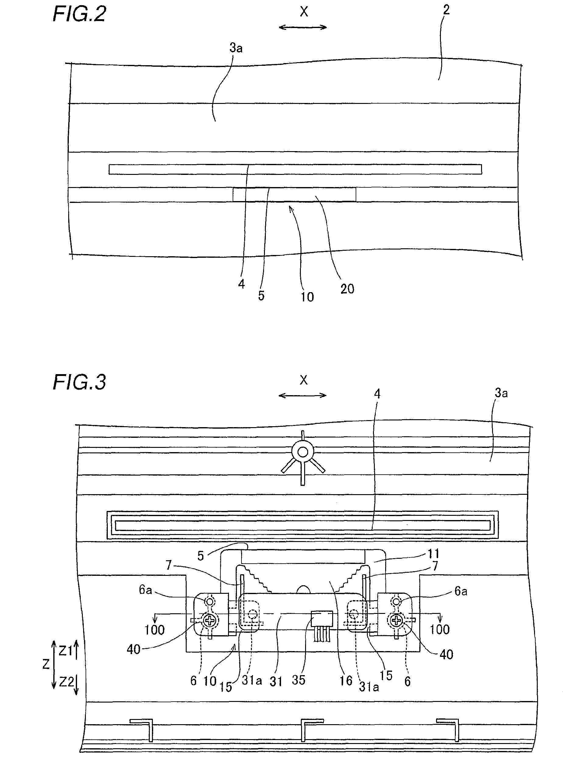
[0048]First, the structure of a television set 1 with a disk unit comprising an indicator unit 10 according to an embodiment of the present invention is described with reference to FIG. 1 to 10. This embodiment of the present invention is applied to the television set 1 with a disk unit employed as an exemplary television set.

[0049]The television set 1 with a disk unit according to the embodiment of the present invention comprises a liquid crystal panel 2 for displaying images, as shown in FIG. 1. The liquid crystal panel 2 is an example of the “display portion” in the present invention. The liquid crystal panel 2 is supported by a housing 3 constituted of a front housing 3a and a rear housing 3b. The front housing 3a has a disk slot 4 provided under the liquid crystal panel 2 for receiving a disk and a display portion slot 5 provided under the disk slot 4 for receiving a display portion 20 ...


PUM


Abstract

This structure for mounting an indicator unit on an electronic apparatus includes an indicator unit including a wiring board and a lens member having a first pressing portion pressing a first surface of the wiring board and a housing of an electronic apparatus, mounted with the indicator unit, including a second pressing portion pressing a second surface of the wiring board. The wiring board is so held between the first pressing portion of the lens member and the second pressing portion of the housing as to be fixed.

Description

BACKGROUND OF THE INVENTION[0001]1. Field of the Invention[0002]The present invention relates to a structure for mounting an indicator unit on an electronic apparatus, and more particularly, it relates to a structure for mounting an indicator unit including a wiring board on an electronic apparatus.[0003]2. Description of the Background Art[0004]A turning apparatus comprising a rotating member rotatable in a horizontal plane is known in general, as disclosed in each of Japanese Patent Laying-Open Nos. 62-219597 (1987), 2005-5374 and 2007-116556, for example.[0005]The aforementioned Japanese Patent Laying-Open No. 62-219597 discloses a structure for mounting a board (wiring board) on a panel (housing). In this mounting structure, two pairs of protrusions vertically separating from each other are provided on a surface of the panel mounted with the board at a prescribed interval in the width direction. These protrusions have pin receiving holes vertically passing therethrough, so that ...

Claims


Application Information

Patent Timeline
Patent Type & Authority Patents(United States)
IPC IPC(8): H05K7/02H05K7/04
CPCH04N5/64
Inventor SUGAMURA, TOMOKAZU
Owner FUNAI ELECTRIC CO LTD
Why Eureka
Try Eureka