Differential device

a technology of differential gears and sleeves, which is applied in the direction of differential gearings, belts/chains/gearrings, differential gearings, etc., can solve the problems that side gears and sleeves cannot be integrated into differential cases, welding or adhesive bonding is an obstacle to improving assembly efficiency, etc., and achieves good assembly ease.

Active Publication Date: 2016-02-16
MUSA PRECISION IND CO LTD
View PDF6 Cites 3 Cited by
  • Summary
  • Abstract
  • Description
  • Claims
  • Application Information

AI Technical Summary

Benefits of technology

[0007]The present invention has been made in view of the above-described circumstances, and an object of the present invention is to provide a differential device in which lubricating oil in a differential case is prevented from leaking out of a space between a side gear and a sleeve without performing a special process such as pressure welding or adhesive bonding during assembly and which has good ease of assembly.
[0009]According to the first aspect of the present invention, the sleeve can be prevented from detaching from the bearing boss by the falling-off prevention device, lubricating oil in the differential case can be prevented from leaking out of the falling-off prevention device by the seal member, and the ease of assembly is good.
[0011]According to the second aspect of the present invention, the falling-off prevention device includes the annular first locking groove formed on the inner periphery of the outer tube portion, the annular first locking protrusion adjacent to the first locking groove, and the elastic piece which is formed in the inner end portion of the inner tube portion to have the second locking protrusion and the second locking groove capable of respectively engaging with the first locking groove and the first locking protrusion and which can bend inward in the radial direction. When the inner tube portion is inserted into the outer tube portion, and the second locking protrusion passes through the first locking protrusion, the elastic piece is bent inward in the radial direction by the first locking protrusion. After the passage of the second locking protrusion through the first locking protrusion, the second locking protrusion and the second locking groove are respectively engaged with the first locking groove and the first locking protrusion by the return of the elastic piece to a free state. Accordingly, the sleeve can easily be prevented from detaching from the bearing boss.
[0014]According to a fourth aspect of the present invention, in addition to the first aspect, the falling-off prevention device includes a fixed engagement portion formed on an inner periphery of the outer tube portion and a movable engagement portion formed in the inner tube portion, the movable engagement portion being capable of elastically deforming to move between a first position where the movable engagement portion is detached from the fixed engagement portion to allow withdraw of the sleeve and a second position where the movable engagement portion is engaged with the fixed engagement portion to prevent falling-out of the sleeve, and having biasing force toward the first position; and, when the drive shaft is spline-fitted to the side gear, the movable engagement portion is expanded in the radial direction by the drive shaft to be forcibly held at the second position.
[0017]According to the fifth aspect of the present invention, the splined shaft of the drive shaft can expand the movable engagement portion to the second position and can transmit rotation to the sleeve.
[0019]According to the sixth aspect of the present invention, the outer tube portion is formed in the sleeve, and the inner tube portion is formed in the side gear. Also, the annular outer locking groove is provided in the inner peripheral surface of the outer tube portion, and the annular inner locking groove facing the outer locking groove is provided in the outer peripheral surface of the inner tube portion. The locking ring having a resilient force in the diameter expansion direction is attached to the outer and inner locking grooves. Thus, the falling-off prevention device is configured. The inner locking groove has a depth which allows the diameter of the locking ring to be reduced by the inner peripheral surface of the outer tube portion when the outer and inner tube portions are fitted to each other. In the fitted surfaces of the outer and inner tube portions, flat portions are formed which come in contact with each other to connect the outer and inner tube portions in the direction of rotation. Thus, while the sleeves have press-formable configurations, ease of assembly is good, the sleeves can be prevented from detaching from the bearing bosses, and rotation can be transmitted from the side gears to the sleeves.

Problems solved by technology

In other words, if the side gear and the sleeve are integrated, a total length thereof becomes longer than an inside diameter of the integrated differential case, and the side gear and the sleeve cannot be incorporated into the differential case.
However, during assembly, a special process such as pressure welding or adhesive bonding is an obstacle to improving efficiency of assembly.

Method used


Image

  • Differential device
  • Differential device
  • Differential device

Examples


first embodiment

[0045]Next, operations of this first embodiment will be described.

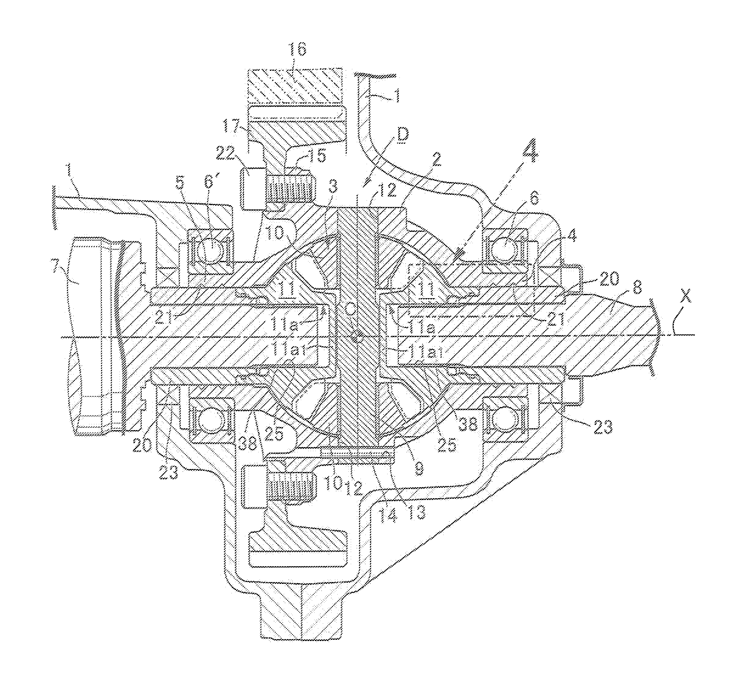
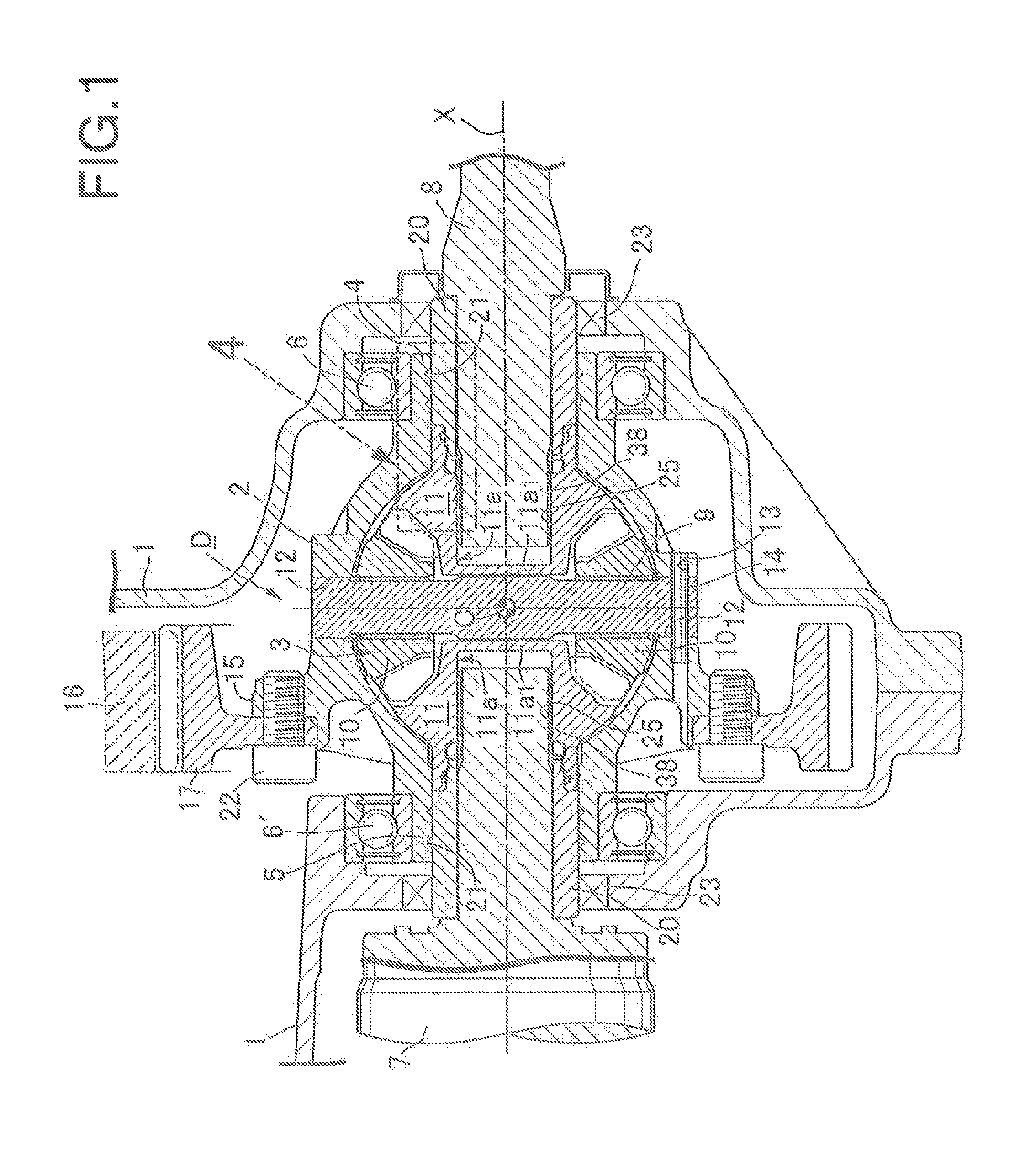
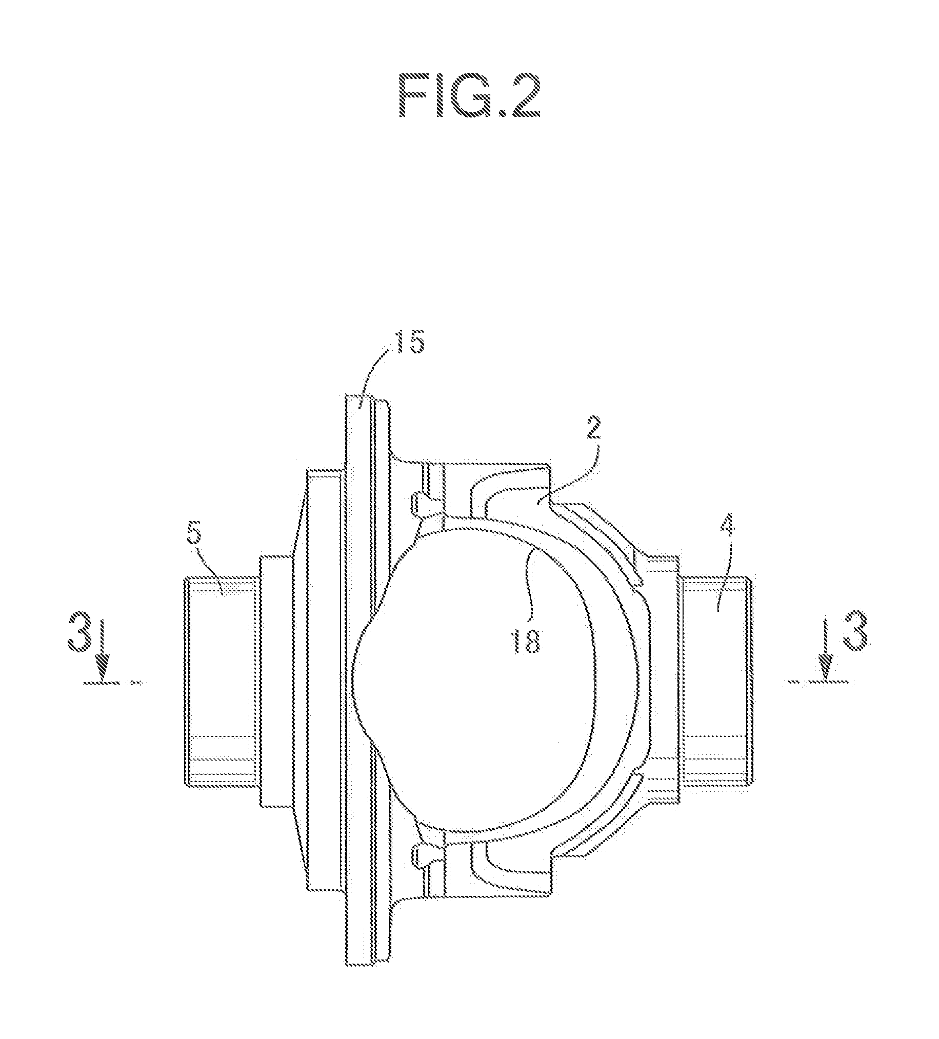
[0046]When the differential device D is assembled, the side gears 11 are first inserted into the differential case 2 through the work window 18, and the outer tube portions 26 are fitted to the inner peripheral surfaces of the corresponding bearing bosses 4, 5. Subsequently, the pinion gears 10 are also inserted into the differential case 2 through the work window 18 and set at predetermined positions, and the pinion shaft 9 is attached to the differential case 2.

[0047]After that, each sleeve 20 is fitted and inserted into the bearing boss 4 or 5 from the outside thereof and pushed in while the inner tube portion 27 is being fitted to the inner peripheral surface of the outer tube portion 26 of the side gear 11. The tapered surfaces 35 of the elastic pieces 34 of the inner tube portion 27 are pushed inward in the radial direction by the first locking protrusion 29 of the outer tube portion 26. Thus, the second locking...

second embodiment

[0053]Next, the present invention shown in FIGS. 6 to 8 will be described.

[0054]In this second embodiment, the outer tube portion 26 is formed in one of the side gear 11 and the sleeve 20, and the inner tube portion 27 is formed in the other. Further, on the inner periphery of the outer tube portion 26, a fixed engagement portion 41 which is formed of an annular protrusion is formed; and in the inner tube portion 27, a plurality of movable engagement portions 42 arranged along a peripheral direction of the inner tube portion 27 are formed. The movable engagement portions 42 can bend to move between first positions A corresponding to detachment from the fixed engagement portion 41 and second positions B corresponding to engagement with the fixed engagement portion 41. Elastic biasing force which biases the movable engagement portions 42 toward the first positions A is applied to the movable engagement portions 42. The fixed engagement portion 41 and the movable engagement portions 42...

third embodiment

[0059]Next, the present invention shown in FIGS. 9 to 11 will be described.

[0060]On a back face of the side gear 11, an inner tube portion 27 is integrally provided in a protruding manner. In an outer peripheral surface of the inner tube portion 27, an annular inner locking groove 45 and an annular seal groove 36 located more inward than the inner locking groove 45 are provided. An O-ring 37 is attached to the seal groove 36. Moreover, on an outer periphery of an outer end portion of the inner tube portion 27, one or more inner flat portions 47 are provided.

[0061]The sleeves 20 which are respectively fitted to the inner peripheral surfaces of the first and second bearing bosses 4, 5 are made by pressing. An inner end portion of the sleeve 20 is formed as an outer tube portion 26 which is fitted to the outer peripheral surface of the above-described inner tube portion 27. The above-described O-ring 37 comes in tight contact with an inner peripheral surface of the outer tube portion 2...


PUM


Abstract

In a differential device, an outer tube portion is formed in one of a side gear and a sleeve, and an inner tube portion fitted to an inner periphery of the outer tube portion is formed in the other. A falling-off prevention device for preventing axial relative movement of the outer and inner tube portions is provided between the outer and inner tube portions. A seal member for shutting off communication between the falling-off prevention device and an inside of a differential case is set in a fitting portion between the outer and inner tube portions. Accordingly, lubricating oil in the differential case is prevented from leaking out of a space between the side gear and the sleeve without performing a special process such as pressure welding or adhesive bonding during assembly and which has good ease of assembly.

Description

BACKGROUND OF THE INVENTION[0001]1. Field of the Invention[0002]The present invention relates to an improvement of a differential device comprising: a differential gear mechanism; and an integrated differential case housing the differential gear mechanism, the differential case including: first and second bearing bosses formed integrally on one side portion and another side portion of the differential case and aligned on a same axis to be rotatably supported by a transmission case; a work window for inserting the differential gear mechanism, the work window being provided in a peripheral wall of the differential case; a pair of sleeves fitted into the first and second bearing bosses from sides of outer ends thereof; oil seals being set between outer end portions of the sleeves which protrude from the first and second bearing bosses, and the transmission case; and left and right drive shafts, which are fitted and inserted into the sleeves, being spline-fitted to a pair of left and ri...

Claims


Application Information

Patent Timeline
Patent Type & Authority Patents(United States)
IPC IPC(8): F16H48/38F16H48/08
CPCF16H48/38F16H48/08
Inventor YANASE, YOICHINIIYAMA, TSUNEFUMI
Owner MUSA PRECISION IND CO LTD
Why Eureka
Try Eureka