Electric fastener driver

a technology of electric fastener and driver, which is applied in the direction of manufacturing tools, percussive tools, portable drilling machines, etc., can solve the problems of inability to move, the operation site of the fastener driver is not always flat, and the site of operation is limited

Inactive Publication Date: 2007-05-03
HITACHI KOKI CO LTD
View PDF10 Cites 28 Cited by
  • Summary
  • Abstract
  • Description
  • Claims
  • Application Information

AI Technical Summary

Benefits of technology

[0009] In view of the above-described problem in the conventional fastener driver, it is an object of the present invention to provide an electric fastener driver in which a clutch is turned on and off precisely at a given rotary position.

Problems solved by technology

In other words, such a combination lacks mobility.
However, sites of fastener driver operation do not always have a flat area for placing a compressor.
In other words, sites of operation are limited for fastener driver that require the use of a compressor.
However, since the electric efficiency of solenoid coils is rather poor and between 5 and 20%, fastener drivers adapted to use a solenoid coil are inevitably heavy and bulky when the required drive power is large.
Then, to hold such a fastener driver by hand for a long time in order to drive nails has been difficult.
However, in the known improved electric fastener driver, the clutch is turned on and off as the balls move in the grooves and the ball does no move uniformly in the grooves.
In other words, to turn on and off the clutch precisely at a given rotary position of the ball outer pan relative to the ball inner pan has been difficult.

Method used


Image

  • Electric fastener driver
  • Electric fastener driver
  • Electric fastener driver

Examples


Embodiment Construction

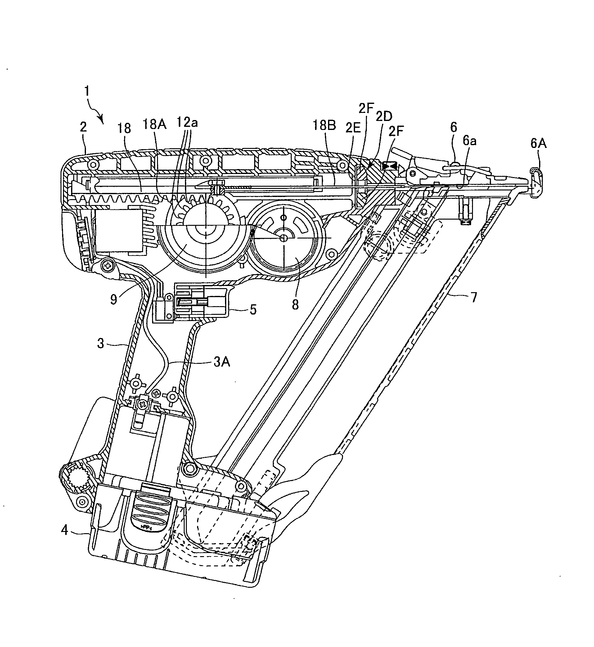
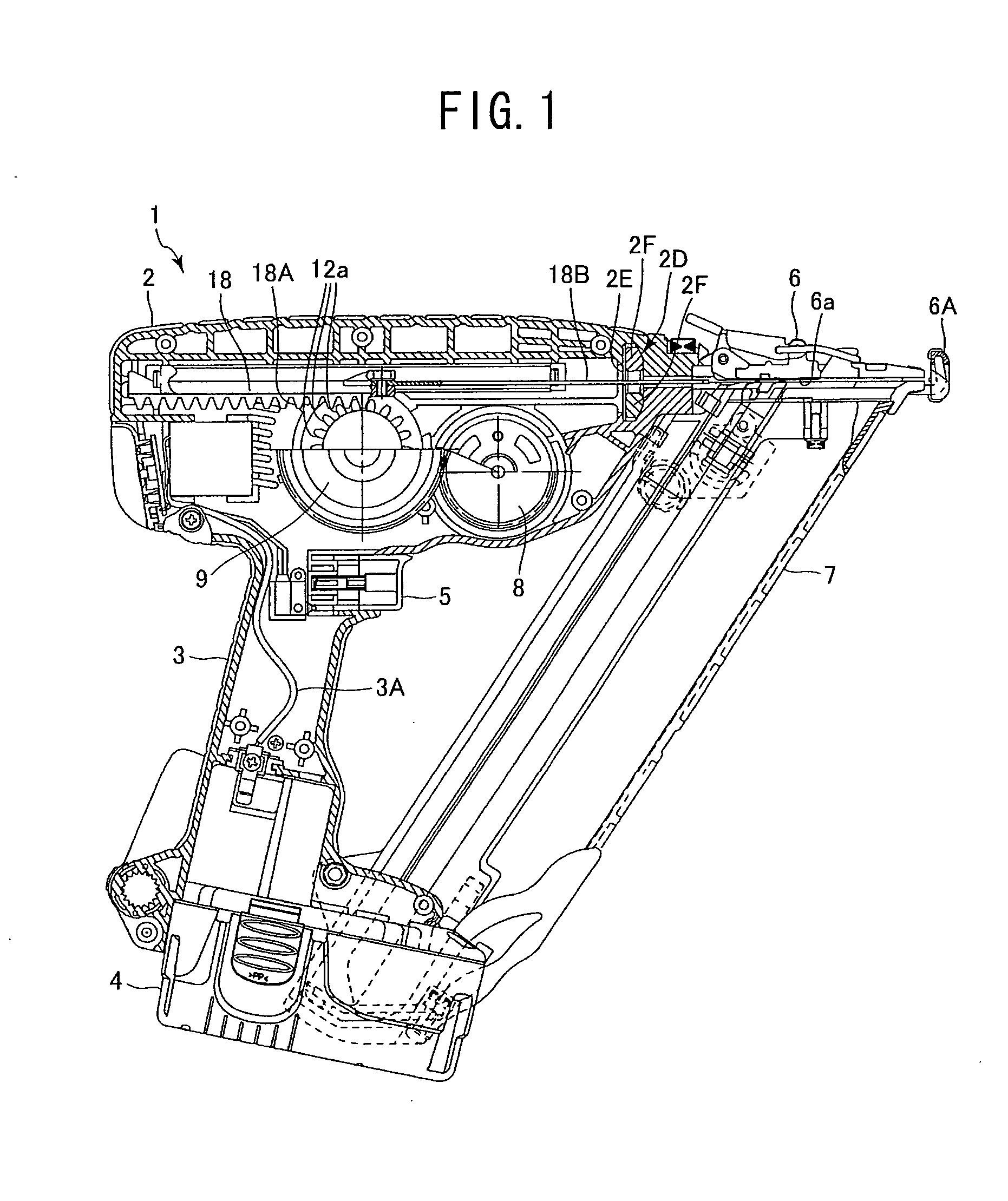
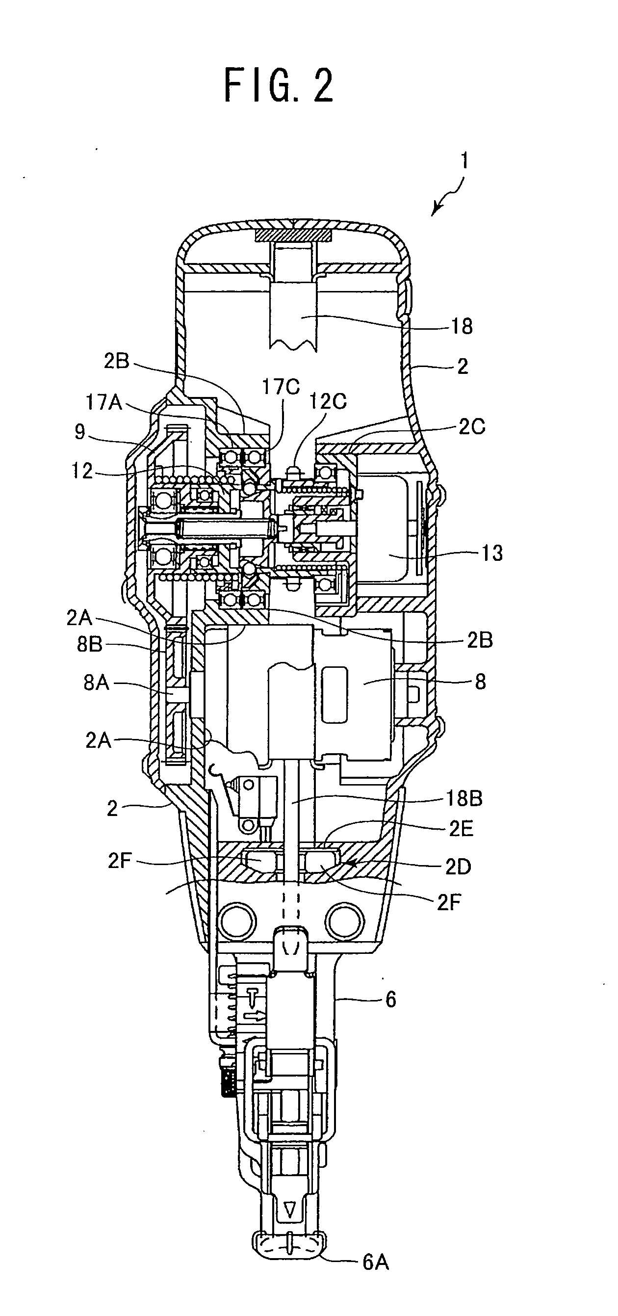
[0023] A fastener driver according to one embodiment of the present invention will be described with reference to FIGS. 1 through 7. The fastener driver 1 schematically illustrated in FIG. 1 includes a housing 2 that is an outer shell, a handle 3, a battery 4, a nose 6 arranged at the front end i.e., the driving side of the housing 2, and a magazine 7.

[0024] A motor 8 and a driver segment 18 are arranged in the housing 2. The driver segment 18 is guided by a rail (not shown) in the housing 2 and is held movable between the front end side and the rear end side of the housing 2, that is, between the right end side and the left end side in FIG. 1. A blade 18B is provided at the front end of the driver segment 18 in such a way that the blade 18B extends to a position in a channel 6a, which will be described later, when the driver segment 18 moves to the front end side or the right side in FIG. 1, to the largest extent. A rack 18A is arranged as a part of the driver segment 18 and locat...


PUM

PropertyMeasurementUnit
rotation angleaaaaaaaaaa
distanceaaaaaaaaaa
outer diameteraaaaaaaaaa

Abstract

A stationary annular abutting member 14E is provided with a first projecting section that operates as part of a ratchet mechanism. A rotational flange section is provided with a second projecting section that operates as part of the ratchet mechanism. The first projecting section projects in the direction from the ON position toward the OFF position of a plunger of a solenoid. The second projecting section projects in the direction from the OFF position toward the ON position of the plunger. When a driven rotor starts rotating and comes to a rotary position slightly short of the rotary position of about ¾ of a full turn in the ON state of the solenoid, the projecting end of the first projecting section and that of the second projecting section are located opposite to each other and the second projecting section rides on the first projecting section.

Description

BACKGROUND OF THE INVENTION [0001] The present invention relates to a fastener driver, and more particularly, to an electric fastener driver. [0002] A compressed air type fastener driver such as a nail gun has been known. Compressed air generated by a compressor is used as a power source for the fastener driver. However, the use of a compressor is a prerequisite for compressed air type fastener drivers. Therefore, when operating a fastener driver while moving the driver from the ground floor to the first floor of a building, the compressor needs to be moved along with the fastener driver. In other words, such a combination lacks mobility. Additionally, a space needs to be provided for placing the compressor. However, sites of fastener driver operation do not always have a flat area for placing a compressor. In other words, sites of operation are limited for fastener driver that require the use of a compressor. [0003] Electric fastener drivers adapted to drive a solenoid coil as main...

Claims


Application Information

Patent Timeline
Patent Type & Authority Applications(United States)
IPC IPC(8): B25C5/02
CPCB25C1/06
Inventor ODA, HIROYUKIUEDA, TAKASHINAKANO, YOSHIHIROTANIMOTO, HIDEYUKI
Owner HITACHI KOKI CO LTD
Why Eureka
Try Eureka