Optical imaging lens

An optical imaging lens and lens technology, applied in the field of lenses, can solve the problems of poor athermalization performance optimization, low relative illumination, uneven image, etc., to ensure clarity and uniformity, high relative illumination, and good use effect. Effect

Pending Publication Date: 2021-03-16
XIAMEN LEADING OPTICS
View PDF0 Cites 2 Cited by
  • Summary
  • Abstract
  • Description
  • Claims
  • Application Information

AI Technical Summary

Problems solved by technology

[0003] However, there are still many shortcomings in the optical imaging lens currently used in the vehicle field, such as poor control of transmission, low resolution, low resolution, and uneven images; more lenses are used, and the cost is high; light transmission is small and relative illumination is low. , prone to vignetting; severe blue-purple fringing, affecting use; poor athermalization performance optimization, image quality is easily affected by temperature, etc., can no longer meet the increasing requirements of the automotive field, and urgently needs to be improved

Method used


Image

  • Optical imaging lens
  • Optical imaging lens
  • Optical imaging lens

Examples


Embodiment 1

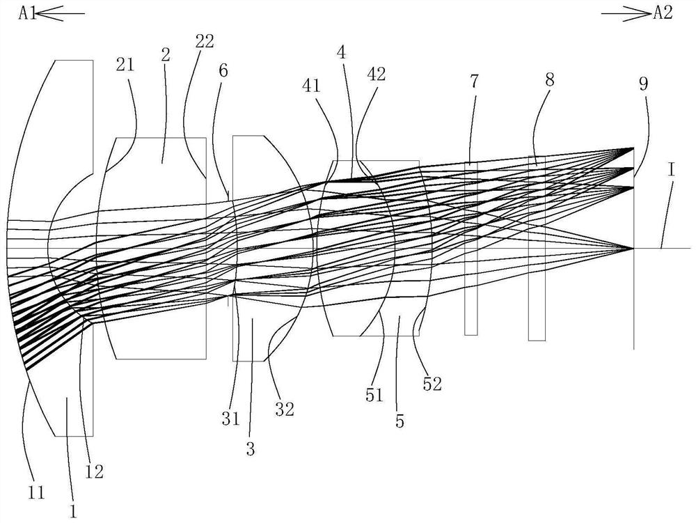
[0058] Such as figure 1 As shown, an optical imaging lens includes a first lens 1, a second lens 2, a diaphragm 6, a third lens 3, a fourth lens 4, and a fifth lens along an optical axis I from the object side A1 to the image side A2. Lens 5, optical filter 7, protective glass 8 and imaging surface 9; First lens 1 to fifth lens 5 each comprise an object side towards object side A1 and allow imaging light to pass through and an object side towards image side A2 and allow imaging light to pass through Through the like profile.

[0059] The first lens 1 has a negative refractive power, the object side 11 of the first lens 1 is convex, and the image side 12 of the first lens 1 is concave.

[0060] The second lens 2 has positive refractive power, the object side 21 of the second lens 2 is a convex surface, and the image side 22 of the second lens 2 is a plane.

[0061] The third lens 3 has positive refractive power, the object side 31 of the third lens 3 is concave, and the image...

Embodiment 2

[0076] The concave-convex surface and refractive power of each lens in this embodiment and the first embodiment are roughly the same, only the image side 22 of the second lens 2 is a convex surface, and in addition, the optical parameters such as the radius of curvature of each lens surface and lens thickness are also different. .

[0077] In this specific embodiment, the first lens 1 is preferably made of H-ZLAF50E glass material.

[0078] The detailed optical data of this specific embodiment are shown in Table 2-1.

[0079] Detailed optical data of Table 2-1 Example 2

[0080]

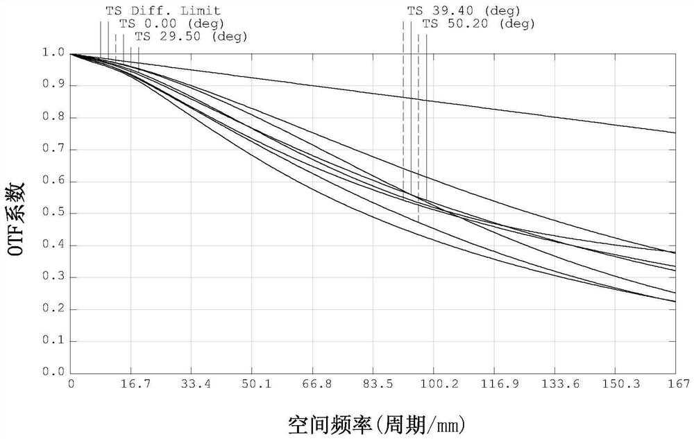
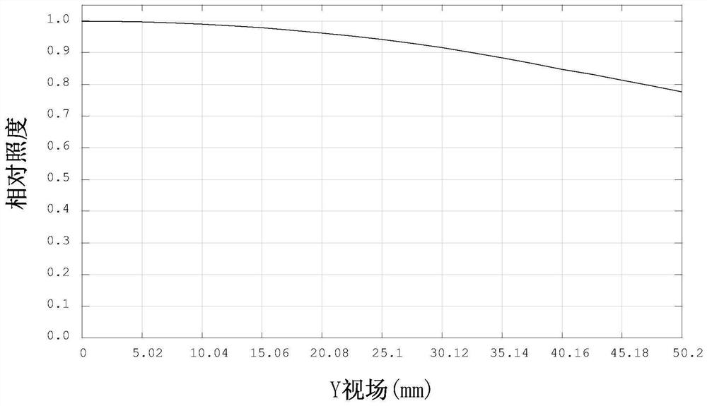
[0081] The MTF transfer function curve figure of this specific embodiment sees for details Figure 6 , it can be seen that the design has a high transfer rate, and the resolution can reach 167lp / mm, which ensures the clarity and uniformity of the image; for the relative illuminance curve, please refer to Figure 7 , it can be seen that the relative illuminance is relatively high, greater than 7...

Embodiment 3

[0085] The concave-convex surface and refractive power of each lens in this embodiment and the first embodiment are roughly the same, only the image side 22 of the second lens 2 is a convex surface, and in addition, the optical parameters such as the radius of curvature of each lens surface and lens thickness are also different. .

[0086] In this specific embodiment, the first lens 1 is preferably made of H-ZLAF52 glass material.

[0087] The detailed optical data of this specific embodiment are shown in Table 3-1.

[0088] Detailed optical data of the third embodiment of table 3-1

[0089]

[0090]

[0091] The MTF transfer function curve figure of this specific embodiment sees for details Figure 10 , it can be seen that the design has a high transfer rate, and the resolution can reach 167lp / mm, which ensures the clarity and uniformity of the image; for the relative illuminance curve, please refer to Figure 11 , it can be seen that the relative illuminance is rela...


PUM


Abstract

The invention relates to the technical field of lenses. The invention discloses an optical imaging lens. The optical imaging lens sequentially comprises a first lens, a second lens, a diaphragm, a third lens, a fourth lens and a fifth lens from an object side to an image side along an optical axis, the first lens is a convex-concave lens with negative refraction; the second lens is a convex planeor convex lens with positive refractive index; the third lens is a concave-convex lens with a positive refractive index; the fourth lens is a convex lens with positive refractive index; the fifth lensis a concave-convex lens with a negative refractive index, and the fourth lens and the fifth lens are glued with each other; and the refractive index temperature coefficient of the first lens is a positive value. The optical imaging lens has the advantages of high resolution, large light transmission, high relative illuminance, good chromatic aberration and aberration correction, small temperature drift and low cost.

Description

technical field [0001] The invention belongs to the technical field of lenses, and in particular relates to an optical imaging lens applied in the field of vehicles. Background technique [0002] With the continuous advancement of science and technology and the continuous development of society, optical imaging lenses have also developed rapidly in recent years. Optical imaging lenses are widely used in smart phones, tablet computers, video conferencing, security monitoring, machine vision, and vehicle monitoring. Therefore, the requirements for optical imaging lenses are getting higher and higher. [0003] However, there are still many shortcomings in the optical imaging lens currently used in the vehicle field, such as poor control of transmission, low resolution, low resolution, and uneven images; more lenses are used, and the cost is high; light transmission is small and relative illumination is low. , easy to appear vignetting; blue-purple fringing is serious, which af...

Claims


Application Information

Patent Timeline
Patent Type & Authority Applications(China)
IPC IPC(8): G02B13/00G02B13/06
CPCG02B13/0015G02B13/005G02B13/006G02B13/06
Inventor 廖明燕李可林清泉
Owner XIAMEN LEADING OPTICS
Why Eureka
Try Eureka