Dibbling equipment for garden planting
A technology of seeding and equipment, applied in the field of seeding equipment for garden planting, can solve the problems of long consumption time, low work efficiency, inability to achieve uniform seeding, etc., and achieve the effect of watering.
- Summary
- Abstract
- Description
- Claims
- Application Information
AI Technical Summary
Problems solved by technology
Method used
Image
Examples
Embodiment 1
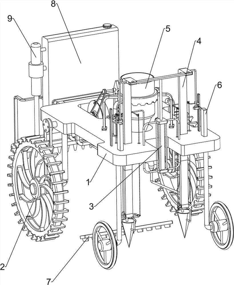
[0057] A kind of spot planting equipment for garden planting, such as figure 1 As shown, it includes a mounting plate 1, a driving assembly 2, a cylinder 3, an earth-opening mechanism 4 and a seeding mechanism 5. The upper front side is provided with a soil-opening mechanism 4, and the middle part of the upper front side of the mounting plate 1 is provided with a seeding mechanism 5.
[0058] When people want to sow soybeans, they can use this point planting equipment for garden planting. First, start the driving assembly 2, and the user pushes the driving assembly 2 to push the equipment to the vicinity of the field, and then injects the soybeans into the sowing mechanism 5 During the process, the soybeans flow into the soil-opening mechanism 4 along the seeding mechanism 5, start the cylinder 3, and the cylinder 3 drives the soil-opening mechanism 4 to operate, so as to open the soil, so that the soybeans are sown in the soil, and the seeding effect is realized. After the so...
Embodiment 2
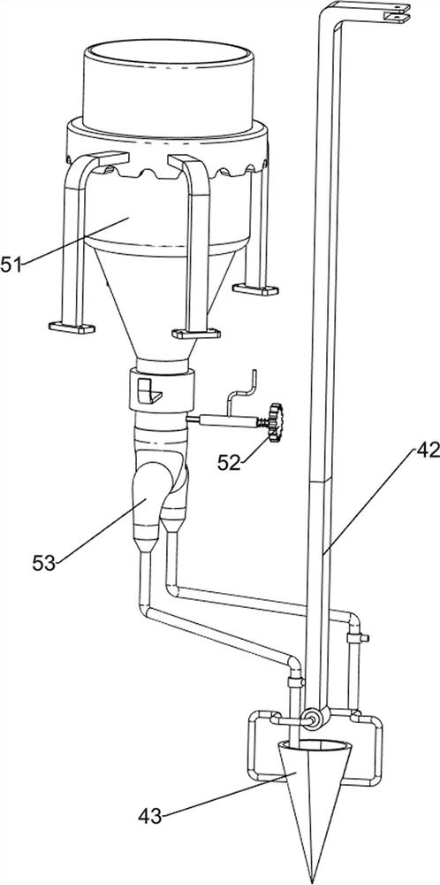
[0060] On the basis of Example 1, such as figure 2 and image 3 As shown, the soil opening mechanism 4 includes a push rod 41, a guide rod 42, a bucket 43, a first guide sleeve 44, a sliding assembly 45 and a connecting rod assembly 46. There are guide rods 42, and push rods 41 are arranged between the tops of the two guide rods 42, and first guide sleeves 44 are arranged on the left and right sides of the upper front side of the mounting plate 1, and the inner sides of the two first guide sleeves 44 are slidingly provided with Sliding assembly 45, two sliding assemblies 45 opposite sides are all provided with connecting rod assembly 46, every guide bar 42 bottoms are all provided with hole-drilling bucket 43, and hole-drilling bucket 43 is connected with connecting rod assembly 46.
[0061] When the telescopic rod of the cylinder 3 is shortened downward, it drives the push rod 41 to move downward, and then drives the guide rod 42 to move downward. Press the sliding assembl...
Embodiment 3
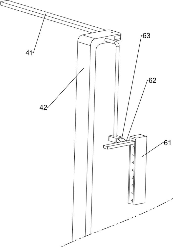
[0065] On the basis of Example 2, such as Figure 4-Figure 7 As shown, a linkage mechanism 6 is also included. The left and right sides of the upper front side of the mounting plate 1 are provided with a linkage mechanism 6. The linkage mechanism 6 includes a second guide sleeve 61, an elastic push plate 62 and a small elastic block 63. The left and right sides of the front side are provided with a second guide sleeve 61, the inner wall of the second guide sleeve 61 is provided with an elastic push plate 62, and the upper part of the guide rod 42 is provided with an elastic small block 63, which is in contact with the elastic push plate 62 .
[0066] When the guide rod 42 moves downward, thereby driving the elastic small block 63 to move downward, the elastic small block 63 contacts and cooperates with the elastic push plate 62, and then drives the elastic push plate 62 to move downward, and the sliding assembly 45 moves downward. When the rod 42 moves upward, it drives the e...
PUM
 Abstract
Description
Claims
Application Information
 - R&D
- Intellectual Property
- Life Sciences
- Materials
- Tech Scout
- Unparalleled Data Quality
- Higher Quality Content
- 60% Fewer Hallucinations
Browse by: Latest US Patents, China's latest patents, Technical Efficacy Thesaurus, Application Domain, Technology Topic, Popular Technical Reports.
© 2025 PatSnap. All rights reserved.Legal|Privacy policy|Modern Slavery Act Transparency Statement|Sitemap|About US| Contact US: help@patsnap.com


