Door lock structure for electric appliance and cleaning machine applying door lock structure
A door lock structure and electrical appliance technology, applied in the field of cleaning machines, can solve the problems of relying on electronic control structure and poor stability, and achieve the effects of low electronic control logic requirements, high reliability and good practicability
- Summary
- Abstract
- Description
- Claims
- Application Information
AI Technical Summary
Problems solved by technology
Method used
Image
Examples
Embodiment 1
[0046] The door lock structure of this embodiment is used to lock any door body and box body, and this embodiment uses a sink type cleaning machine as an example for illustration. like Figure 11 As shown, the cleaning machine of this embodiment includes a box body 8 and a door body 9, the box body 8 has a washing chamber and an upper port 81 connected to the top of the washing chamber, and an edge of the door body 9 is connected to the upper port of the box body 8 by rotation. 81 at the edge.
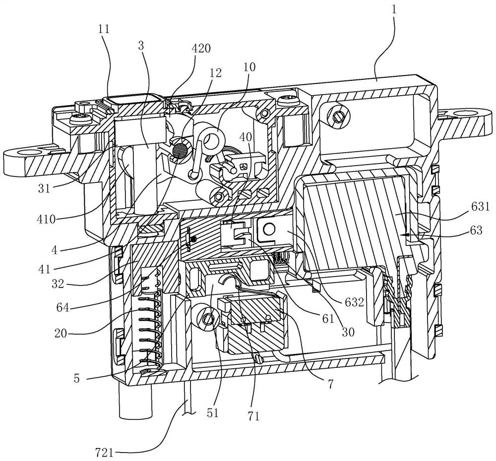
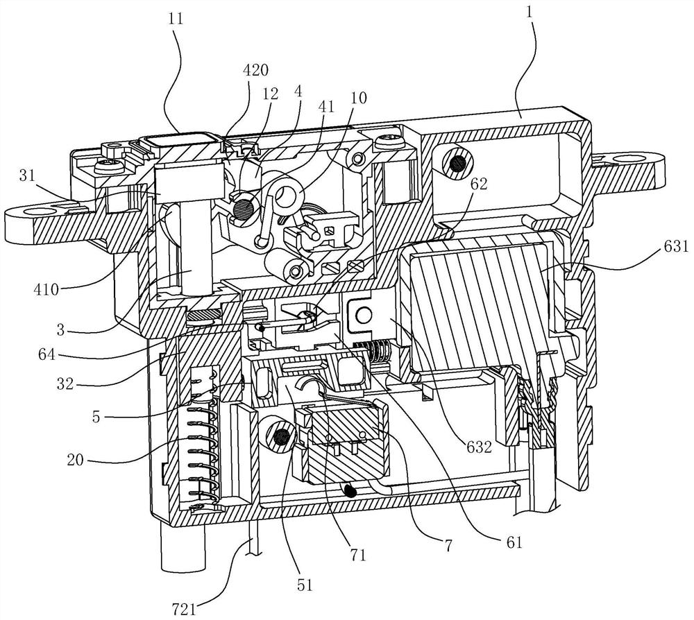
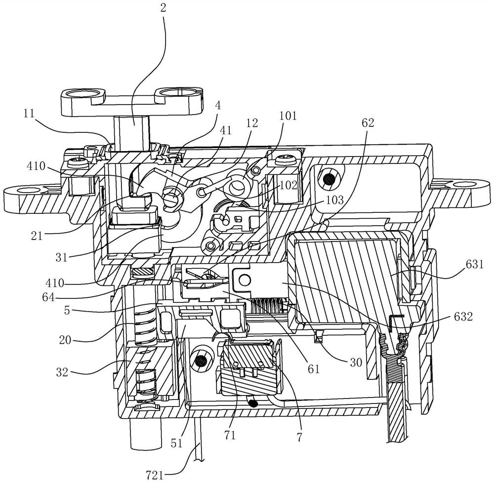
[0047] The door lock structure used for electrical appliances in this embodiment includes a housing 1, a lock bar 2, an ejector 3, a lock catch 4, a second elastic member 20, a first elastic member 10, a limit block 5 and a driving mechanism, and the lock bar 2 Vertically installed on the lower wall of the door body 9 and arranged near the edge, the housing 1, the ejector 3, the first elastic member 10, the second elastic member 20, the lock 4, the limit block 5 and the driving mechan...
Embodiment 2
[0059] like Figures 12 to 16 As shown, the difference between this embodiment and the embodiment is:
[0060] The first elastic part of this embodiment is the first torsion spring 5', the first torsion spring 5' includes a middle helical body 51' and extension arms at both ends, the middle helical body 51' of the first torsion spring 5' is freely suspended and is located away from the lock On one side of the C-shaped opening of the buckle 4, the end of the first arm 52' of the first torsion spring 5' is connected to the outer edge 402 of the middle part of the buckle 4, and the end of the second arm 53' of the first torsion spring 5' is constrained in the on shell 1. When the upper end 420 of the C-shaped structure is located at the side of the ejector 3, the first torsion spring 5' keeps the buckle 4 in a clockwise direction around the shaft 41; the upper end 420 of the C-shaped structure is located above the ejector 3 and is aligned with When the locking hook 21 is engage...
PUM
 Abstract
Description
Claims
Application Information
 - R&D
- Intellectual Property
- Life Sciences
- Materials
- Tech Scout
- Unparalleled Data Quality
- Higher Quality Content
- 60% Fewer Hallucinations
Browse by: Latest US Patents, China's latest patents, Technical Efficacy Thesaurus, Application Domain, Technology Topic, Popular Technical Reports.
© 2025 PatSnap. All rights reserved.Legal|Privacy policy|Modern Slavery Act Transparency Statement|Sitemap|About US| Contact US: help@patsnap.com


