Glass cover plate circumferential polishing mechanism and circumferential polishing equipment

A cover plate circumference and glass technology, which is applied in the field of glass cover plate circumference throwing mechanism and circumference throwing equipment, can solve the problems of inability to remove debris and slag, limited effect, heat accumulation of driving motor, etc., so as to improve the polishing effect and prevent static electricity. The effect of setting precipitation and improving yield

Active Publication Date: 2021-04-09
凯盛科技股份有限公司
View PDF10 Cites 2 Cited by
  • Summary
  • Abstract
  • Description
  • Claims
  • Application Information

AI Technical Summary

Problems solved by technology

[0003] However, there are still obvious defects in its use: 1. The above-mentioned device cannot add polishing liquid when polishing the glass cover plate, and is not suitable for high-level precision glass polishing, so its effect is very limited; 2. 1. The above-mentioned device cannot remove the debris and debris on the polished glass cover in time, causing these debris and debris to easily scratch the glass, resulting in a high rate of defective products; 3. During the polishing process of the glass cover, the drive motor They are all in working condition. In the continuous processing production line, the drive motor will continue to accumulate heat due to long-term use, which not only affects its service life, but also poses safety hazards. The above-mentioned devices cannot effectively solve this problem.

Method used


Image

  • Glass cover plate circumferential polishing mechanism and circumferential polishing equipment
  • Glass cover plate circumferential polishing mechanism and circumferential polishing equipment
  • Glass cover plate circumferential polishing mechanism and circumferential polishing equipment

Examples


Embodiment

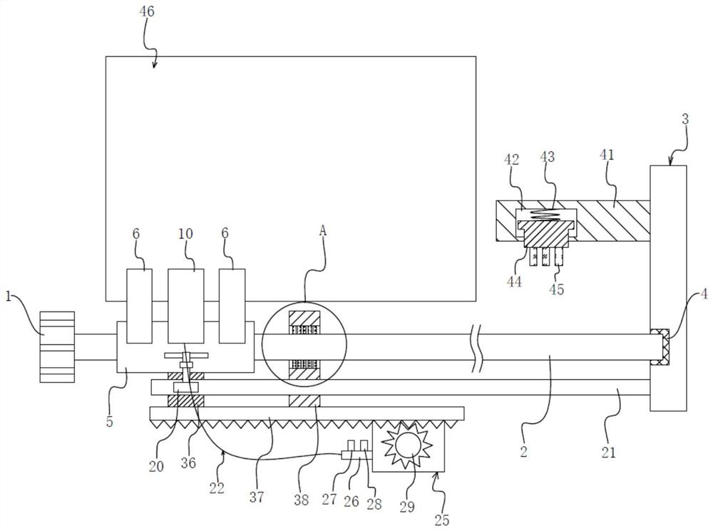
[0034] see Figure 1 to Figure 5 , the present invention provides a technical solution:

[0035] A weekly throwing mechanism for a glass cover, comprising:

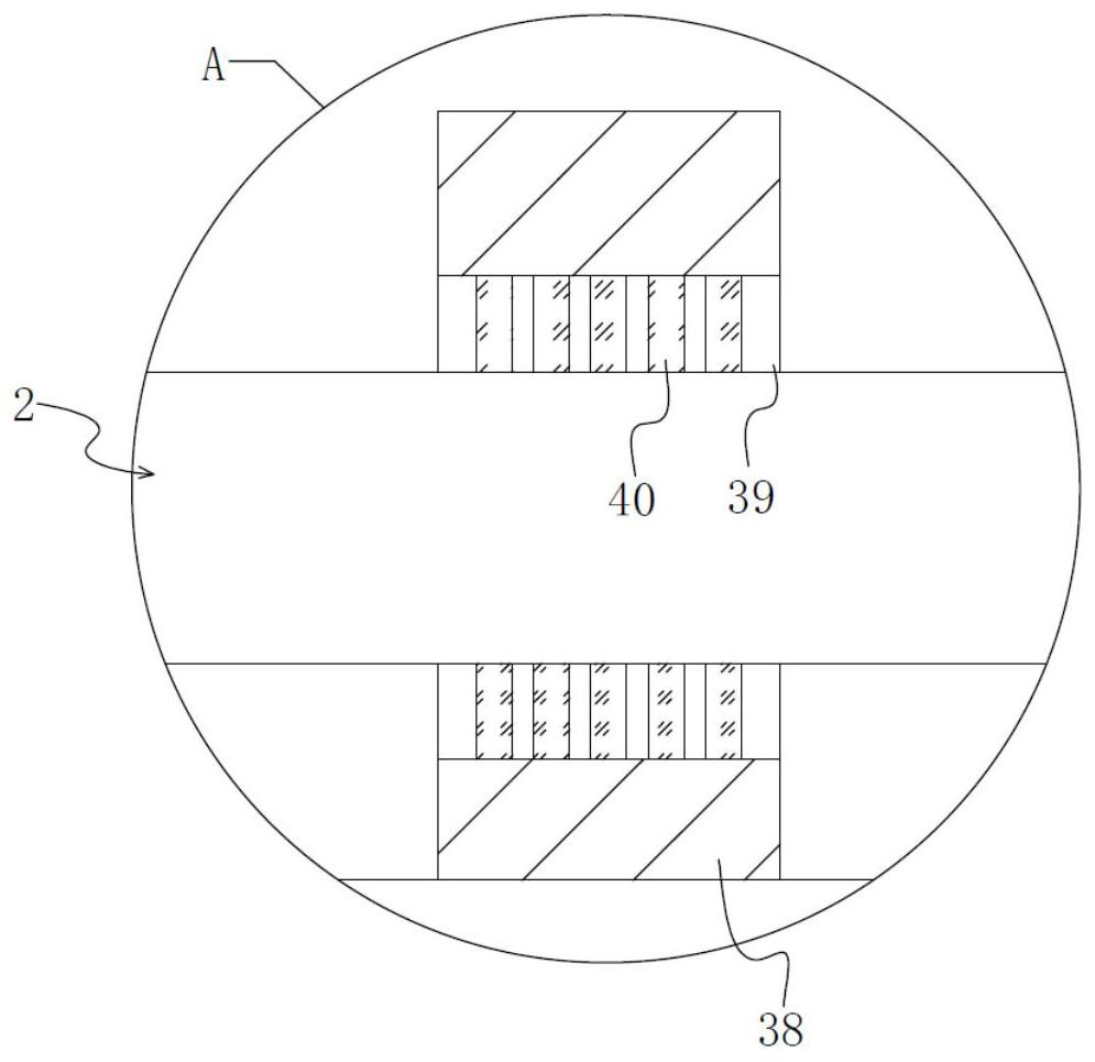
[0036] A rotary motor 1, the output end of the rotary motor 1 is fixedly provided with a screw rod 2, the end of the screw rod 2 away from the rotary motor 1 is hingedly arranged in the side plate 3, and a nut block 5 is movable on the screw rod 2, when the rotary motor 1 starts It will drive the screw rod 2 to rotate, and then make the nut block 5 move along the screw rod 2;

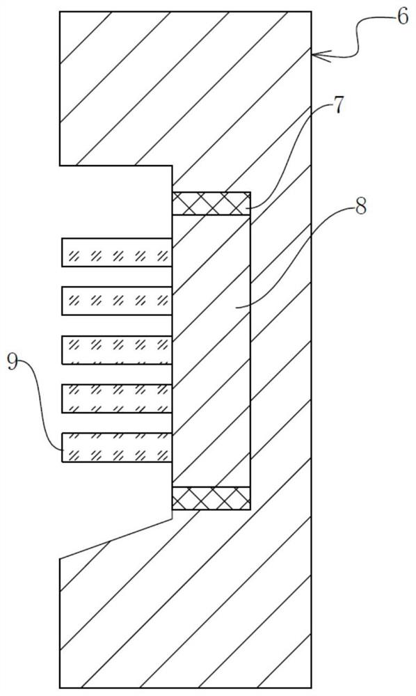
[0037] The dust removal block 6 is fixedly arranged on the nut block 5, and the ring bearing 7 is embedded in the dust removal block 6, and the circular bottom plate 8 is hingedly arranged in the ring bearing 7, and the glass is fixedly arranged on the circular bottom plate 8. Cover plate cleaning brush 9 is used to clean the periphery of the glass cover plate 46. When cleaning, the circular bottom plate 8 can rotate in the ring bearing 7, thereb...


PUM


Abstract

The invention provides a glass cover plate circumferential polishing mechanism and circumferential polishing equipment. The glass cover plate circumferential polishing mechanism comprises a rotating motor, wherein a screw rod is fixedly arranged at the output end of the rotating motor, and a nut block is movably arranged on the screw rod; a dust removing block, wherein a glass cover plate cleaning brush is fixedly arranged on a circular bottom plate; a polishing block, wherein a polishing wheel is fixedly arranged on a rotating shaft, and a plurality of spraying covers are arranged on a water tank in a communicating mode; a polishing liquid box, wherein a stirring shaft is fixedly arranged in the center of a second transmission wheel, and a second rack plate can drive the second transmission wheel to rotate; and a cleaning rod, wherein a lead screw cleaning brush can be in contact with a lead screw and is used for cleaning the lead screw. According to the glass cover plate circumferential polishing mechanism and the circumferential polishing equipment, polishing liquid can be sprayed, generated glass chippings and disintegrating slag can be removed in time, the polishing liquid can be stirred to avoid precipitation, the lead screw is cleaned to avoid blocking movement of a nut block, a polishing motor is cooled in real time, functions are concentrated, and the glass cover plate circumferential polishing mechanism and the circumferential polishing equipment are quite worthy of popularization.

Description

technical field [0001] The invention relates to the technical field of glass processing, in particular to a glass cover plate weekly throwing mechanism and weekly throwing equipment. Background technique [0002] In the prior art, a fully automatic weekly throwing machine with the application number "201920785719.9" includes a frame; two weekly throwing mechanisms installed symmetrically on the top of the frame, and the weekly throwing mechanism includes a horizontal drive device arranged laterally along the top of the frame , the horizontal moving slide plate installed on the horizontal driving device, the longitudinal driving device installed on the horizontal moving sliding plate, the longitudinal moving sliding plate installed on the longitudinal driving device, the bearing seat installed on the longitudinal moving sliding plate, the rotation axis is vertically downward It runs through the bearing seat and extends to the middle of the frame. The brush wheel is installed ...

Claims


Application Information

Patent Timeline
IPC IPC(8): B24B29/02B24B41/06B24B47/12B24B57/02B24B41/04B24B55/00B08B11/04B08B1/00B08B13/00B01F7/18
CPCB24B29/02B24B41/06B24B47/12B24B57/02B24B41/04B24B55/00B08B11/04B08B13/00B01F27/90B08B1/12B08B1/30
Inventor 王伟张少波陈诚杨金发许波张煜东周道钧罗丹邵帅黄涛涛
Owner 凯盛科技股份有限公司
Why Eureka
Try Eureka