Buffer type container

A container and cushioning technology, which is applied in the field of cushioning containers, can solve the problems of no consideration, no shock absorption function, instability, etc., and achieve the effect of preventing slight tilting

Active Publication Date: 2021-04-16
衡阳泰豪通信车辆有限公司 +1
View PDF5 Cites 0 Cited by
  • Summary
  • Abstract
  • Description
  • Claims
  • Application Information

AI Technical Summary

Problems solved by technology

[0004] 1. In the box transportation of the prior art, the structure of the shelf is relatively fixed, and it is impossible to adjust according to the size specifications of different goods
[0005] 2. In the box transportation of the prior art, the shock absorption only depends on the spring. However, the spring shock absorption is a relatively simple shock absorption method with poor shock absorption performance and instability. It cannot adapt to various shock absorption requirements, and the transportation There are some fragile goods in the process that require higher shock absorption
[0006] 3. The inflatable soft bag of the prior art cannot realize the function of preventing tilting, and if a slight tilt occurs during the transportation of goods, it is more likely to vibrate
The existing inflatable soft capsule is only used for shock absorption, and only applied to its working principle, there is no multi-group linkage shock absorption structure, such as soft capsule linkage group
[0007] 4. The shock absorbing structure in the prior art is often a single shock absorbing structure, which does not realize the combination of two shock absorbing functions
[0008] 5. The inflatable soft capsule of the prior art only has two operations of injecting medium and discharging medium, and has only one structure, without considering the timeliness, cushioning, and stable performance factors on the filling path
[0009] 6. The inflatable soft capsule of the prior art only considers the filling, but does not consider the accuracy and filling volume of the filling

Method used


Image

  • Buffer type container
  • Buffer type container
  • Buffer type container

Examples


Embodiment Construction

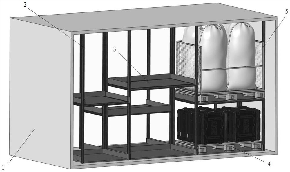
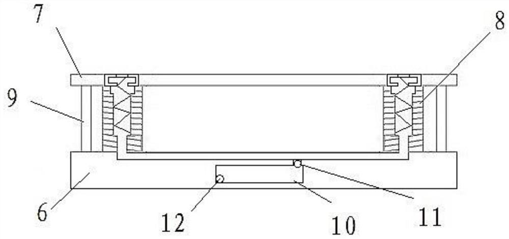
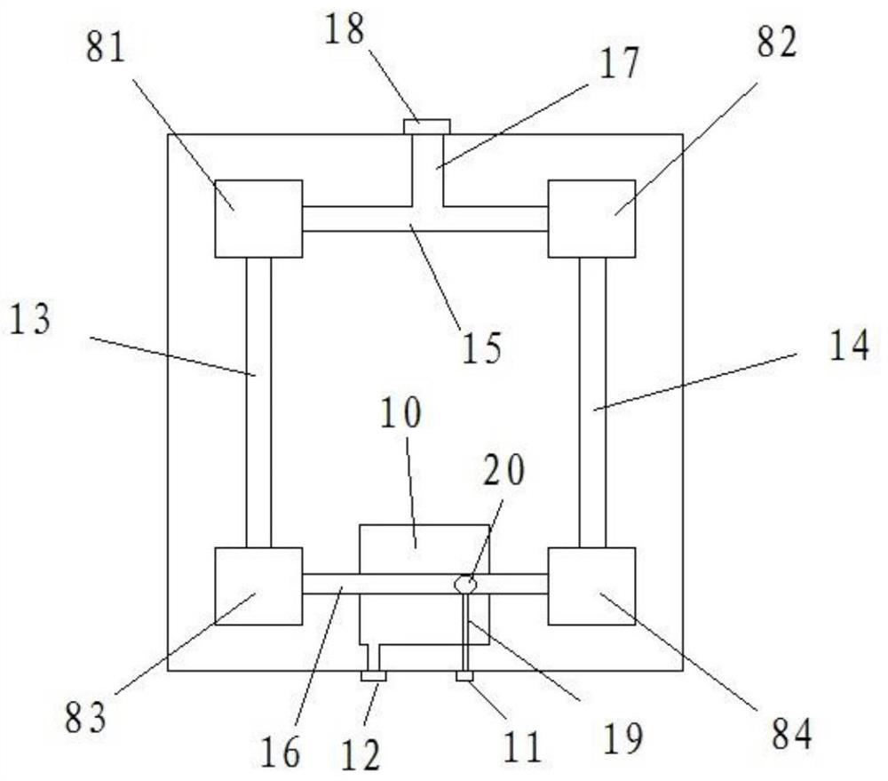
[0041] As shown in the figure: a buffer container, including: a container shell, a shelf column, a pallet, a flexible support, and a shielding plate, wherein the flexible support includes a bottom plate, a top plate, and a shock-absorbing structure, wherein the pallet can move along the shelf. The column slides, and after sliding to a predetermined position, a detachable fixing piece is connected between the tray and the shelf column; the tray is provided with the flexible bracket, and the flexible bracket is provided with the shielding plate;

[0042] The container shell includes: a container top corner piece, a container column, a rear wall, a container bottom corner piece, a container beam, a right wall, a container longitudinal beam, a top wall, a front wall, a left wall, a bottom wall, and a forklift groove; Wall, bottom wall, front wall, left wall, right wall, and rear wall together form the main body of the container shell, wherein the rear wall is configured as a rear d...


PUM


Abstract

The invention discloses a buffer type container which comprises a container outer shell. The container outer shell comprises container top corner pieces, container stand columns, a rear wall, container bottom corner pieces, container cross beams, a right wall, container longitudinal beams, a top wall, a front wall, a left wall, a bottom wall and two forklift grooves; and the top wall, the bottom wall, the front wall, the left wall, the right wall and the rear wall jointly define a container shell body, the rear wall is constructed to be a rear double-door, the right wall is constructed to be a right double-door, and the forklift grooves are located in the lower portion of the right wall.

Description

technical field [0001] The invention relates to the field of container transportation, in particular to a buffer container. Background technique [0002] In the field of transportation, containers are used on a large scale. Containers are composed of container bodies, shelves, and materials. According to the department’s material needs, the materials required by the department are pre-stored on the shelves in the container, and then the original container is placed (released) Realize the rapid distribution of materials where the department needs; the shelves in the container can store a variety of goods, and the structure of some shelves can even be adjusted; storing foldable transfer trolleys in the container can realize the rapid pick-and-place of materials in the cabin . [0003] The concrete deficiency of prior art container is as follows: [0004] 1. In the box transportation of the prior art, the structure of the shelf is relatively fixed, and it is impossible to adj...

Claims


Application Information

Patent Timeline
IPC IPC(8): B65D90/52B65D90/00
Inventor 邓连辉冯文明郭恒穆晓曦蔚国强王世秒赵柏程吕建荣周宏福黄伏军李振国
Owner 衡阳泰豪通信车辆有限公司
Why Eureka
Try Eureka