Method and device for forwarding computing power application flow

A technology that applies flow and forwarding methods, applied in the field of communication

Pending Publication Date: 2021-05-04
ZTE CORP
View PDF0 Cites 6 Cited by
  • Summary
  • Abstract
  • Description
  • Claims
  • Application Information

AI Technical Summary

Problems solved by technology

The node computing power resources in the computing power network are no longer processing messages and streams, but applications, which makes the current network message and stream processing mechanism no longer suitable for the computing power network

Method used


Image

  • Method and device for forwarding computing power application flow
  • Method and device for forwarding computing power application flow
  • Method and device for forwarding computing power application flow

Examples


Embodiment 1

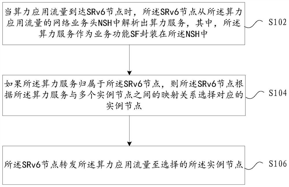
[0037]In this embodiment, a force application flow forwarding method is provided.figure 1 It is a flow chart of a force application flow forwarding method according to an embodiment of the present invention, such asfigure 1 As shown, the process includes the following steps:

[0038]Step S102, when the force applied traffic reaches the SRV6 node, the SRV6 node parses the power service from the network traffic head NSH of the power application traffic, wherein the power service is encapsulated as a service function Sf. NSH;

[0039]Step S104, if the power service is belonging to the SRV6 node, the SRV6 node selects the corresponding example node according to the mapping relationship between the intensive service and the plurality of instance nodes;

[0040]Step S106, the SRV6 node forwards the integrated force application traffic to the selected example node.

[0041]In step S104 of the present embodiment, if the current power service belongs to other SRV6 nodes, the SRV6 node is applied to the ...

Embodiment 2

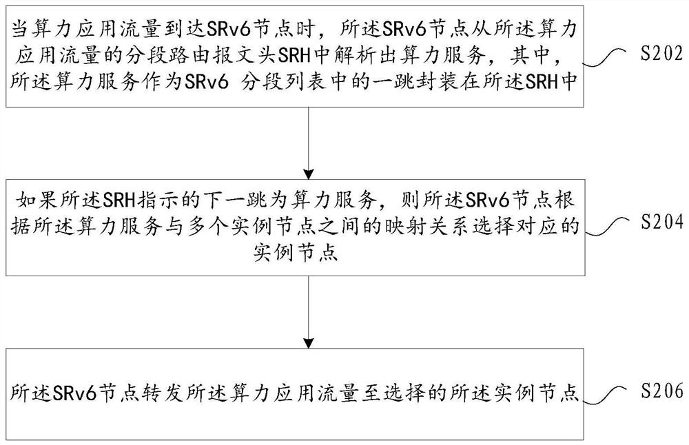
[0046]In this embodiment, another power application flow forwarding method is provided.figure 2 It is a flow chart of a force application flow forwarding method according to an embodiment of the present invention, such asfigure 2 As shown, the method includes the following steps:

[0047]Step S202, when the force application flow reaches the SRV6 node, the SRV6 node parsed the power service from the settlement of the power application traffic, wherein the power service is segmented as an SRV6. A hop package in the list is in the SRH;

[0048]Step S204, if the next hop is shown in the SRH, the SRV6 node selects the corresponding example node according to the mapping relationship between the intensive service and the plurality of instance nodes;

[0049]Step S206, the SRV6 node forwards the integrated force application flow to the selected example node.

[0050]In step S204 of the present embodiment, it may also include: if the next hop of the SRH indication is other SRV6 node, the SRV6 node then...

Embodiment 3

[0061]image 3 It is a structural block diagram of a force application flow forwarding device according to an embodiment of the present invention, such asimage 3 As shown, the power application flow forwarding device includes a first parsing module 10, a first selection module 20, and a first forwarding module 30.

[0062]The first parsing module 10 is used to parse the power service from the network traffic head NSH of the power application traffic to the network traffic head NSH of the power application flow, wherein the power service is encapsulated as a service function. The NSH is in.

[0063]The first selection module 20 is configured to select the corresponding example node based on the mapping relationship between the intensive service and the plurality of instance nodes in the case where the force service is attributed to the SRV6 node.

[0064]The first forwarding module 30 is configured to forward the integrated force application flow to the selected example node.


PUM


Abstract

The embodiment of the invention provides a computing power application flow forwarding method and device, and the method comprises the steps that when computing power application flow reaches an SRv6 node, the SRv6 node analyzes computing power service from a network service head NSH or an IPv6 source routing extension head SRH of the computing power application flow, wherein the computing power service serves as a service function SF to be packaged in the NSH, or to be directly packaged in an IPv6 source routing extension head SRH; if the computing power service belongs to the SRv6 node, the SRv6 node selects a corresponding instance node according to a mapping relationship between the computing power service and a plurality of instance nodes; and the SRv6 node forwards the computing power application flow to the selected instance node. In the invention, a computing power function SF in an NSH or a computing power function Segment in an IPv6 source routing extension head SRH is abstracted, and a mapping relationship with multiple instances is established, so that the dynamic multiple instances of a computing power atomic function are supported, and the scheduling of the computing power service is realized based on an SRv6 forwarding mechanism.

Description

Technical field[0001]Embodiments of the present invention relate to communication fields, in particular, to a force application flow forwarding method and apparatus.Background technique[0002]With the rapid development of high bandwidth, low-delay business, the proportion of low-delay business is growing, and the integrated deployment is evolved from the traditional centralized deployment in business traffic. . Connect the terminal, edge nodes, and cloud nodes to connect the terminal, edge nodes, and the network synergistic to distribute business traffic, that is, handle business traffic to the current optimal force node, which has become more and more attention to the industry. . Business traffic is processed by various business needs to be routed to the corresponding power node, which will be the mainstream business scenario and business needs of the power network.[0003]The intersection network requires a network based on the integration of resources to routing the business traffic...

Claims


Application Information

Patent Timeline
IPC IPC(8): H04L29/06H04L12/721H04L29/12G06F9/50G06F9/48
CPCH04L69/22H04L45/34G06F9/5027G06F9/4881H04L2101/659Y02D30/70H04L67/63H04L2101/668H04L2101/604H04L61/5069H04L45/00H04L67/1004
Inventor 黄光平
Owner ZTE CORP
Why Eureka
Try Eureka