
Anti-overflow injection mold closing equipment with return guide function

An anti-spill, functional technology, applied in the field of injection molding equipment, can solve the problem of molten plastic burning and other problems

Inactive Publication Date: 2021-05-11
李江鸿
View PDF0 Cites 4 Cited by
  • Summary
  • Abstract
  • Description
  • Claims
  • Application Information

AI Technical Summary

Problems solved by technology

[0003] Since the retrograde anti-overflow type injection molding machine returns the molten plastic through the extrusion tube, if there is a lot of molten plastic overflowing from the mold, the molten plastic that is prone to return will squeeze the molten plastic inside the extrusion tube into the heated When the heating bucket heats the new plastic raw material again, the molten plastic extruded by the extrusion tube will be scorched by the heating bucket

Method used


Image

  • Anti-overflow injection mold closing equipment with return guide function
  • Anti-overflow injection mold closing equipment with return guide function
  • Anti-overflow injection mold closing equipment with return guide function

Examples


Embodiment 1

[0026] For example figure 1 -example Figure 5 Shown:

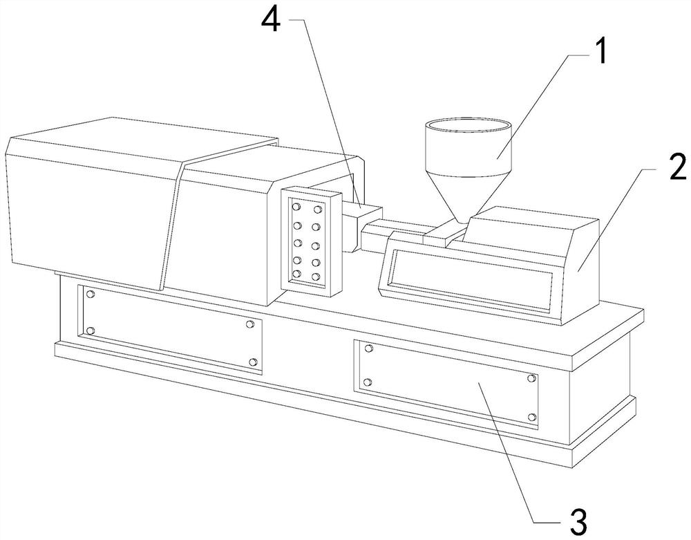
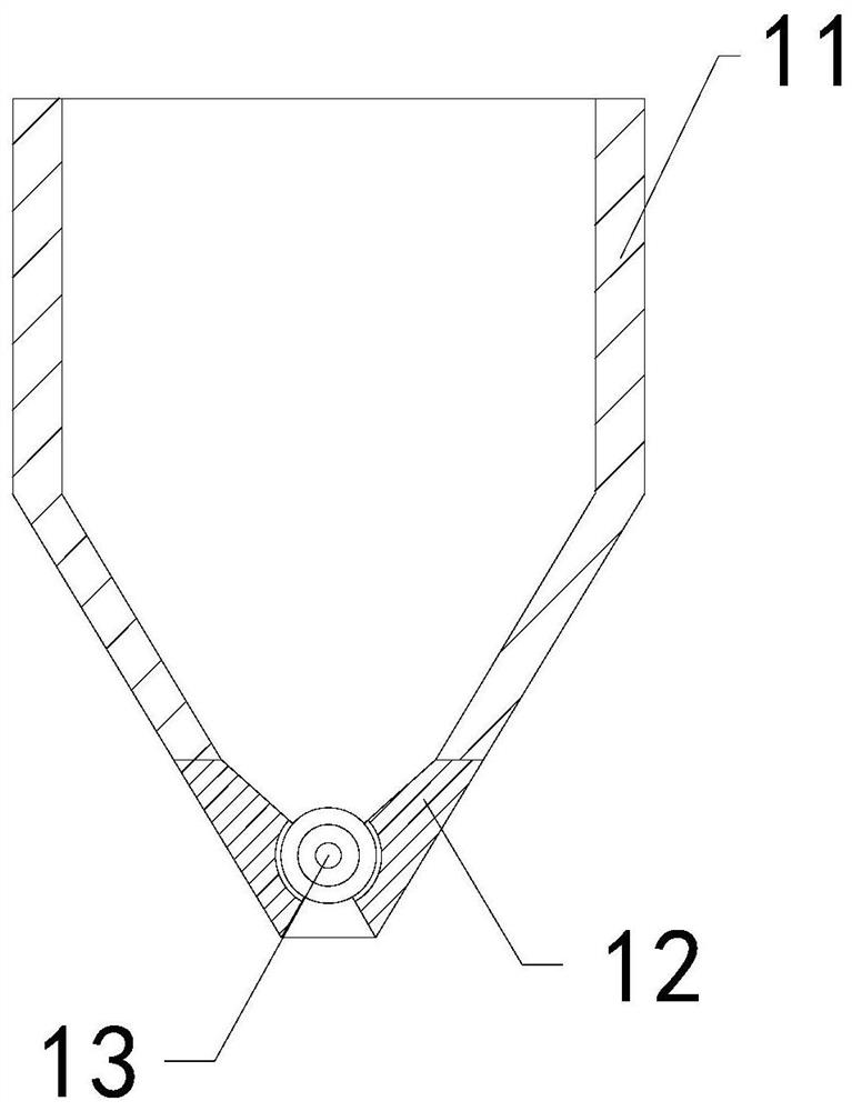
[0027] The present invention provides an injection mold clamping device with a guide function to prevent overflow. Its structure includes a heating bucket 1, a support block 2, a base 3, and an extrusion tube 4. The support block 2 is embedded and fixed on the upper surface of the base 3. , the extrusion tube 4 is connected to the front end of the support block 2, the heating bucket 1 is installed at the upper end of the support block 2; the heating bucket 1 includes an outer frame 11, a lower frame 12, and a blocking mechanism 13, the The lower connecting frame 12 and the outer frame 11 are an integrated structure, and the blocking mechanism 13 is movably engaged with the lower connecting frame 12 .

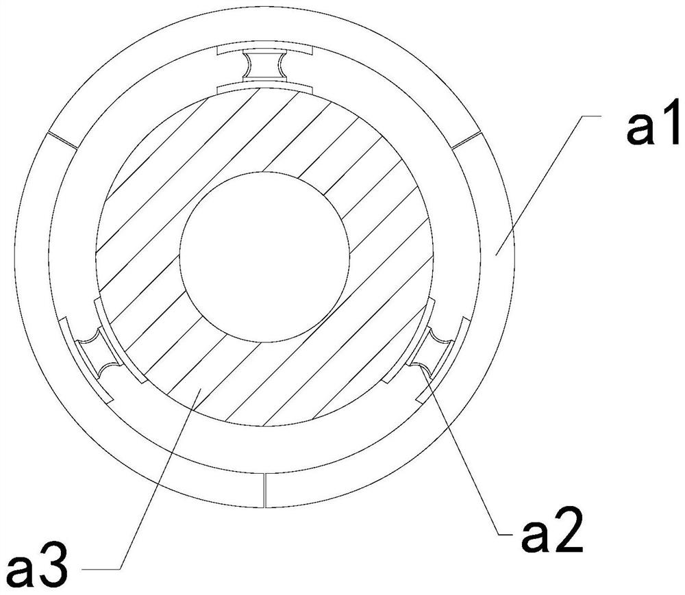
[0028] Wherein, the blocking mechanism 13 includes an outer expansion plate a1, an elastic frame a2, and a middle solid ring a3. The outer surfaces are connected, and there are three outer expansion plates a1, which are ...

Embodiment 2

[0034] For example Figure 6 -example Figure 8 Shown:

[0035] Wherein, the plate body a12 includes a plate surface c1, an elastic ring c2, and a protruding block c3. The elastic ring c2 is installed between the protruding block c3 and the plate surface c1, and the gap between the protruding block c3 and the plate surface c1 is Cooperate, there are four protruding blocks c3, and they are evenly distributed in an arc shape on the board surface c1, and the inertial force generated by the outward protruding of the mechanism can make the protruding block c3 cooperate with the elastic ring c2 stick out.

[0036] Wherein, the protruding block c3 includes a pedestal c31, a contact plate c32, a clearing mechanism c33, and a telescopic rod c34. The contact plate c32 is movably engaged with the pedestal c31 through the telescopic rod c34. At the upper end of the inner wall of the pedestal c31, there are two contact plates c32, which are evenly distributed symmetrically on the left a...


PUM


Abstract

The invention discloses anti-overflow injection mold closing equipment with a return guide function. The equipment structurally comprises a heating hopper, a supporting block, a base and an extrusion pipe, the supporting block is fixedly embedded in the upper surface of the base, the extrusion pipe is connected with the front end of the supporting block, and the heating hopper is installed at the upper end of the supporting block; when molten plastic reversely extruded by the extrusion pipe generates thrust on a blocking mechanism, an external connection ring on the blocking mechanism can rotate clockwise along a connecting rod, so that a movement stopping block can be clamped on the side face of the connecting rod, and the external connection ring can be forced to stop rotating; and the situation that the molten plastic reversely extruded by the extrusion pipe can enter the heating hopper again is effectively avoided, a stress plate can rotate along a middle rod through reverse thrust generated by solidified plastic on the stress plate, and therefore an outer swing plate can be unfolded along the stress plate, and the solidified plastic can be smashed through the outer swing plate.

Description

technical field [0001] The invention relates to the field of equipment for injection mold clamping, in particular to an injection mold clamping equipment with a return function to prevent overflow. Background technique [0002] The anti-overflow injection mold clamping machine is mainly used for injection mold clamping of plastic raw materials. The plastic raw materials can be heated through the heating bucket, and then the molten plastic raw materials can be squeezed into the mold through the extrusion tube, and The overflowing molten plastic can be guided back inward through the extrusion tube. Based on the above description, the inventors have found that the existing injection mold clamping equipment with a return function to prevent overflow mainly has the following deficiencies, for example: [0003] Since the retrograde anti-overflow type injection molding machine returns the molten plastic through the extrusion tube, if there is a lot of molten plastic overflowing fro...

Claims


Application Information

Patent Timeline
Patent Type & Authority Applications(China)
IPC IPC(8): B29C45/18B29C45/17
CPCB29C45/1753B29C45/18
Inventor 张桂珍
Owner 李江鸿
Learn More