High-speed railway bridge support mounting equipment

A technology for bridge bearings and high-speed railways, which is applied in bridge construction, bridges, bridge parts, etc., and can solve problems such as soaking, breaking, and slipping of rising rods

Inactive Publication Date: 2021-06-11
曾丽琼
View PDF0 Cites 1 Cited by
  • Summary
  • Abstract
  • Description
  • Claims
  • Application Information

AI Technical Summary

Problems solved by technology

[0003] If the cement powder of the bridge deck construction floats to the bottom of the bridge deck and the bridge deck is washed with clean water, the cement powder at the bottom of the bridge deck is likely to be soaked, so that the top of the lifting rod of the jack for the installation of the high-speed railway bridge support is at the bottom of the bridge. The cement that touches the bottom of the bridge deck will adhere to the water, which will cause the top of the rising pole to be broken due to the pressure of the air-dried cement after being used again, resulting in the slipping of the rising pole at the bottom of the bridge deck

Method used


Image

  • High-speed railway bridge support mounting equipment
  • High-speed railway bridge support mounting equipment
  • High-speed railway bridge support mounting equipment

Examples


Embodiment 1

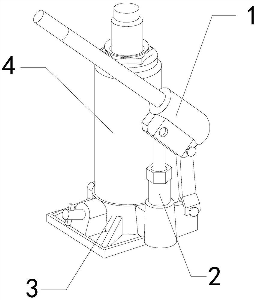
[0026] For example figure 1 -example Figure 5 Shown:

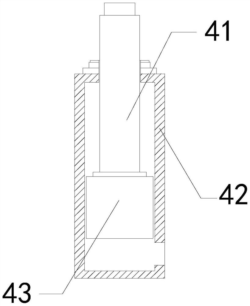
[0027] The invention provides a high-speed railway bridge support installation equipment, the structure of which includes a handle 1, a hydraulic chamber 2, a base 3, and a support mechanism 4, the handle 1 is hinged to the upper end of the hydraulic chamber 2, and the hydraulic chamber 2 is connected to the support The sides of the mechanism 4 are connected, and the support mechanism 4 is installed at the upper end of the base 3; the support mechanism 4 includes a rising rod 41, an outer tube 42, and a piston 43, and the inner movement of the rising rod 41 and the outer tube 42 snapping, the piston 43 is connected with the bottom of the rising rod 41 .

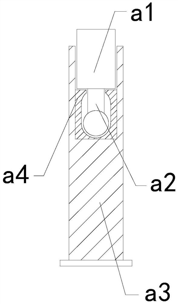
[0028] Wherein, the rising rod 41 includes an upward extension block a1, a linkage rod a2, a bottom plate a3, and an inner connection block a4. Internal movable engagement, the inner connection block a4 and the bottom plate a3 are an integrated structure, through the ...

Embodiment 2

[0034] For example Figure 6 -example Figure 8 Shown:

[0035]Wherein, the plate body a14 includes a combination plate c1, a vibration plate c2, a pull-down piece c3, and a telescopic block c4, the bottom of the vibration plate c2 is connected to the upper end of the telescopic block c4, and the pull-down piece c3 is installed on the The inner position of the plate c2 and the connecting plate c1, the telescopic block c4 cooperates with the internal clearance of the connecting plate c1, through the vibration generated by the mechanism shrinking to the extreme, the telescopic block c4 can push the vibration plate c2 upward to protrude, and through the lower The pulling of the vibrating plate c2 by the pulling piece c3 can quickly reset the vibrating plate c2, so that vibration can be generated to loosen the cement on the upper surface of the vibrating plate c2.

[0036] Wherein, the vibrating plate c2 includes a middle rod c21, a bottom plate c22, a vibrating block c23, and a...


PUM


Abstract

The invention discloses high-speed railway bridge support mounting equipment which structurally comprises a handle, a hydraulic cavity, a base and a supporting mechanism, the handle is connected with the upper end of the hydraulic cavity through a hinge, the hydraulic cavity is connected with the side of the supporting mechanism, and the supporting mechanism is mounted at the upper end of the base. When a lifting rod vibrates when being contracted to an extreme position, so that an upward extension block slides upwards to slide out along an inner connecting block under cooperation of a linkage rod, and further a guiding plate on the up extension block slides towards the middle under cooperation of a pull-back sheet, and vibration can be generated to shake cement at the upper end of the upward extension block into a crushing mechanism; and by means of vibration generated by resetting of a vibration plate, an upper swing plate can swing upwards under the cooperation of a bottom plate, so that the upper swing plate can swing downwards to be closed under the action of the gravity of the upper swing plate, and cement adhered to the outer surface of the upper swing plate can be vibrated to fall off through the impact of the vibration collision block on the inner side of the upper swing plate.

Description

technical field [0001] The invention relates to the field of bridges, in particular to a high-speed railway bridge bearing installation device. Background technique [0002] The jack for the installation of high-speed railway bridge bearings is mainly used to support the bridge deck when installing the bearings of high-speed railway bridges. Press the machine to press the handle so that the rising rod of the jack for the installation of the high-speed railway bridge support can lift the bridge deck, and then put the support between the bottom of the bridge deck and the pier, and the bridge deck of the high-speed railway bridge is easy to adhere to cement during construction Based on the above description, the inventors found that the existing high-speed railway bridge bearing installation equipment mainly has the following deficiencies, for example: [0003] If the cement powder of the bridge deck construction floats to the bottom of the bridge deck and the bridge deck is w...

Claims


Application Information

Patent Timeline
Patent Type & Authority Applications(China)
IPC IPC(8): E01D21/00E01D19/04B66F3/25B66F3/42B66F13/00
CPCB66F3/25B66F3/42B66F13/00E01D19/04E01D21/00
Inventor 张秀月
Owner 曾丽琼
Why Eureka
Try Eureka