Anti-collision equipment for steering shaft of overhead working truck

A technology for aerial work vehicles and anti-collision equipment, which is applied to lifting devices, building maintenance, building construction, etc., can solve problems such as affecting the normal reception of signals by signal receivers, air-drying and solidification of cement powder, and easy falling of cement powder.

Inactive Publication Date: 2021-06-11
陈玲
View PDF0 Cites 0 Cited by
  • Summary
  • Abstract
  • Description
  • Claims
  • Application Information

AI Technical Summary

Problems solved by technology

[0003] Since personnel usually cool the blade by spraying water when cutting the exterior wall of the building, the cement powder generated by cutting the wall is easy to fall on the upper end of the signal receiver, and then soaked by the splashed water mist. If it is not cleaned in time, the cement powder will easily dry and solidify on the signal receiver if it stays for a long time, which will affect the normal reception of the signal by the signal receiver

Method used


Image

  • Anti-collision equipment for steering shaft of overhead working truck
  • Anti-collision equipment for steering shaft of overhead working truck
  • Anti-collision equipment for steering shaft of overhead working truck

Examples


Embodiment 1

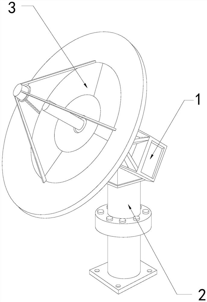
[0026] For example figure 1 -example Figure 5 Shown:

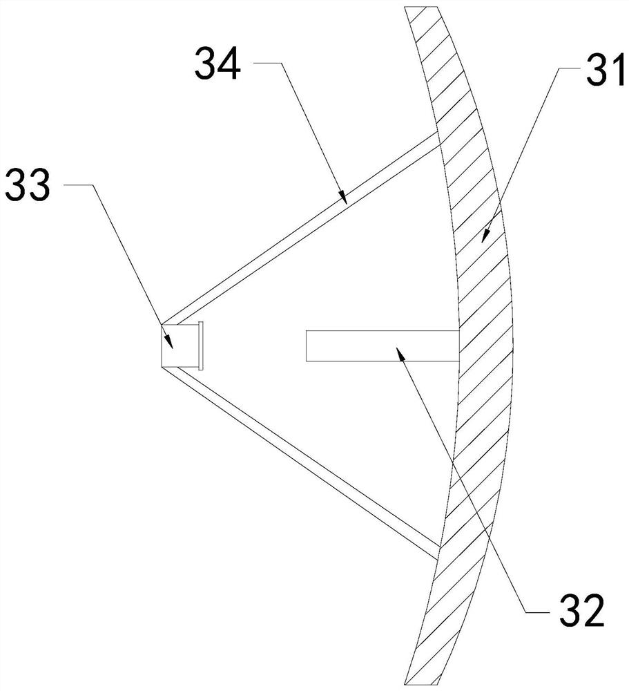
[0027] The invention provides an anti-collision device for the steering shaft of an aerial work vehicle. Its structure includes a steering shaft 1, a support rod 2, and a radar 3. The upper end position of the axis 1; the radar 3 includes a signal booster plate 31, a signal transmitting end 32, a signal receiver 33, and a fixed rod 34, and the signal transmitting end 32 is fixed on the left middle position of the signal booster plate 31, and the The signal receiver 33 is mounted on the inner side of the fixing rod 34 , and the fixing rod 34 is welded to the left side of the signal strengthening board 31 .

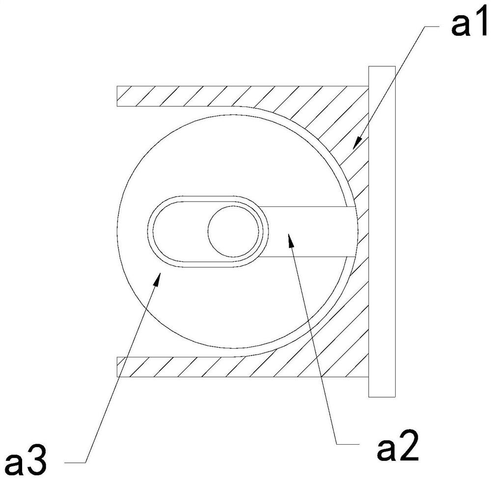
[0028] Wherein, the signal receiver 33 includes an engaging plate a1, a middle connecting rod a2, and a rotating roller a3. The middle connecting rod a2 is fixed on the right side of the inner wall of the engaging plate a1, and the middle part of the rotating roller a3 and the middle The internal sliding fit of the ...

Embodiment 2

[0034] For example Figure 6 -example Figure 8 Shown:

[0035] Wherein, the overhanging plate b1 includes a rear plate b11, an air-drying mechanism b12, an external plate b13, and an absorbing block b14. The air-drying mechanism b12 is embedded in the inner position of the rear plate b11, and the inner side of the external plate b13 Fitted with the outer side of the rear panel b11, the absorbing block b14 runs through the inner position of the outer panel b13, the absorbing block b14 is made of wear-resistant polyether sponge material, and the absorbing block b14 can hold the external panel b13 Moisture on the outside is absorbed.

[0036] Wherein, the air-drying mechanism b12 includes a swing blade c1, a rebound ring c2, and a frame body c3, the swing blade c1 is hinged to the inner side of the frame body c3, and the rebound ring c2 is fixed on the inner side of the frame body c3, There are two swinging blades c1, which are evenly distributed symmetrically inside the uppe...


PUM


Abstract

The invention discloses an anti-collision equipment for a steering shaft of an overhead working truck. The anti-collision equipment structurally comprises a steering shaft, a supporting rod and a radar, the steering shaft is movably clamped with the upper end of the supporting rod, and the radar is installed at the upper end of the steering shaft. Through throwing force generated by the rotation of a rotating roller, an outward extending plate can extend outwards under the cooperation of a transition block when rotating to the right front of a holding and fixing plate, so that the outward extending plate can shake out crushed cement powder outwards, and the situation that the cement powder generated by wall cutting is wetted by water mist and then attached to the outer side of a signal receiver to be air-dried and solidified is effectively avoided; and water in the cement powder on the outer side of the outwards extending plate can be absorbed through an absorbing block, then through inertia force generated by outwards extending of the outwards extending plate, an impact block can outwards extend along a combining block under cooperation of an elastic rod, therefore the impact block can generate impact vibration on the inner wall of an outer frame, and therefore, the cement powder with the moisture completely absorbed on an external plate can be vibrated off.

Description

technical field [0001] The invention relates to the field of aerial work, in particular to an anti-collision device for a steering shaft of an aerial work vehicle. Background technique [0002] The anti-collision steering shaft of the aerial work vehicle is mainly used for anti-collision equipment on the platform of the aerial work vehicle. The anti-collision steering shaft of the aerial work vehicle transmits a signal to the target, and then receives the reflected signal from the target through the anti-collision steering shaft of the aerial work vehicle. signal, in order to calculate the distance between the anti-collision steering axis of the aerial work vehicle and the target, and then the anti-collision effect can be played on the aerial work vehicle. Based on the above description, the inventor found that the steering of an existing aerial work vehicle Shaft anti-collision equipment mainly has the following deficiencies, for example: [0003] Since personnel usually c...

Claims


Application Information

Patent Timeline
IPC IPC(8): B66F11/04B66F13/00B08B7/02E04G23/08
CPCB08B7/02B66F11/04B66F13/00E04G23/08
Inventor 陈玲
Owner 陈玲
Why Eureka
Try Eureka