
Bathroom drainage equipment

A technology for drainage equipment and bathrooms, which is applied to drainage structures, waterway systems, water supply devices, etc., and can solve the problems of foam reverse overflow, large amounts of foam, time-consuming foam, etc.

Inactive Publication Date: 2021-06-15
段幼芬
View PDF0 Cites 0 Cited by
  • Summary
  • Abstract
  • Description
  • Claims
  • Application Information

AI Technical Summary

Problems solved by technology

[0003] As the soap will continue to soften, although the falling soap can be blocked through the bathroom drainage floor drain, the softened soap will be broken into small pieces by the force of the water and enter the floor drain from the hole in the top cover of the floor drain, so that the soap is easy to adhere to It is on the inner wall of the floor drain, so after the waste water is flushed in, a large amount of foam will be generated inside the floor drain, and the more foam will accumulate, the reverse overflow will occur, which will lead to the situation that it will take time to clean the foam again in the later stage

Method used


Image

  • Bathroom drainage equipment
  • Bathroom drainage equipment
  • Bathroom drainage equipment

Examples


Embodiment 1

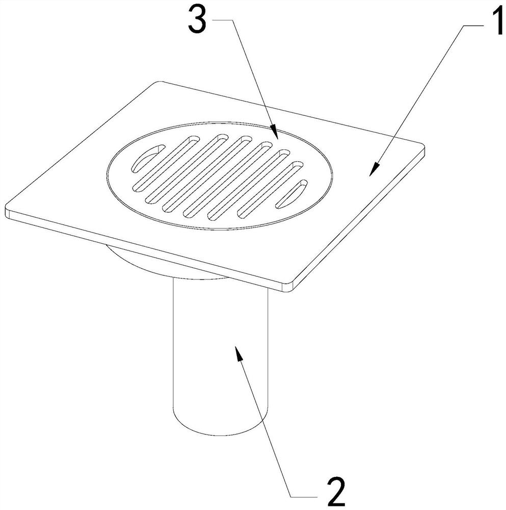
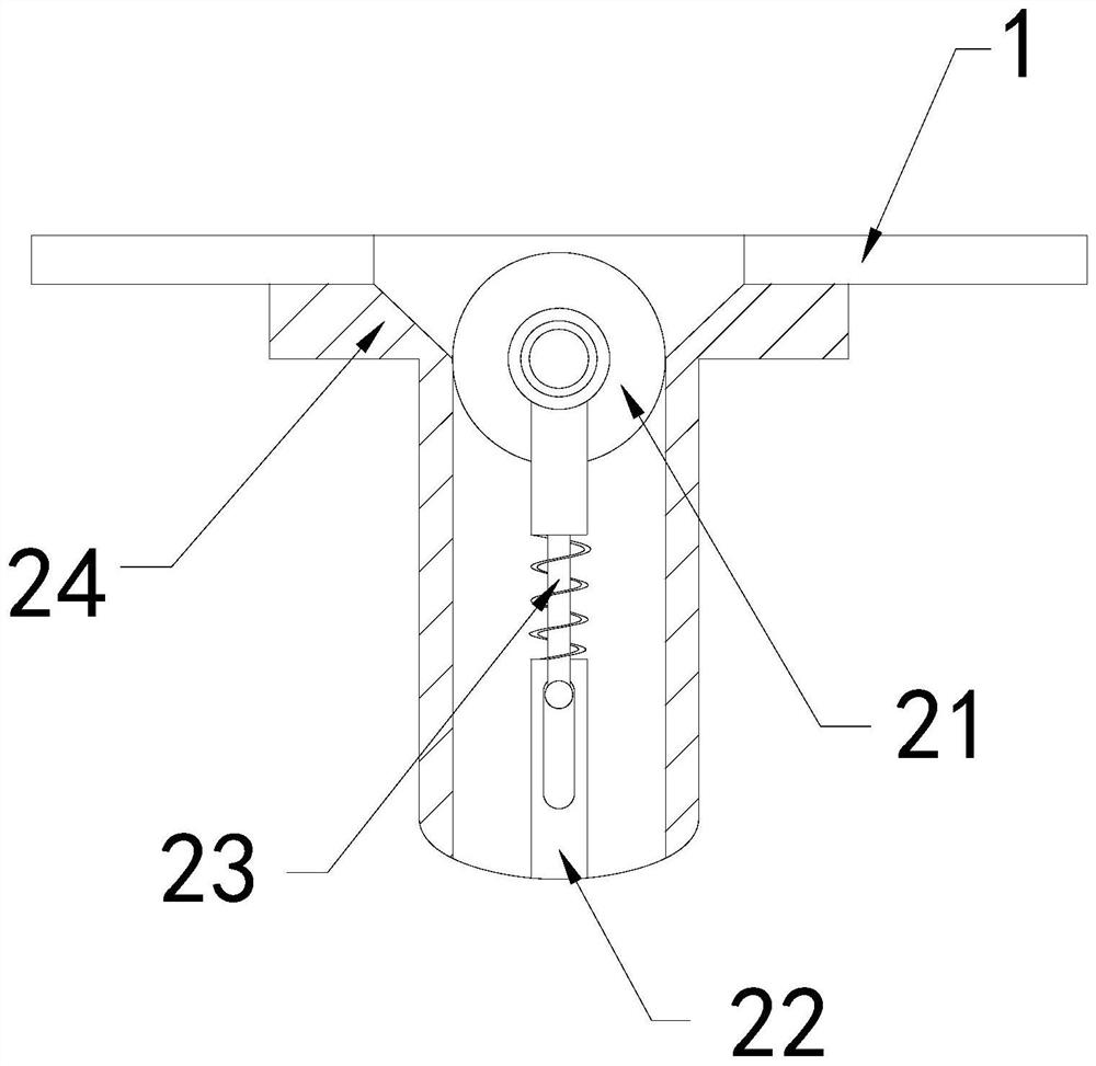
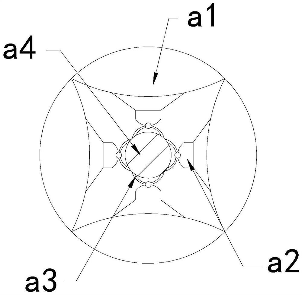
[0026] For example figure 1 -example Figure 5 Shown:

[0027] The present invention provides a bathroom drainage device, the structure of which includes an connecting plate 1, a top cover 2, and a lower connecting pipe 3, the lower connecting pipe 3 is embedded in the inner position of the connecting plate 1, and the top cover 2 is welded to the bottom of the connecting plate 1 position; the top cover 2 includes a stressed roller 21, an inner connecting rod 22, a telescopic rod 23, and an outer tube 24. The stressed roller 21 is movable and engaged with the top of the telescopic rod 23, and the inner connecting rod 22 runs through the At the middle position of the outer tube 24 , the telescopic rod 23 is slidingly matched with the inside of the inner connecting rod 22 .

[0028] Wherein, the stressed roller 21 includes an outer expansion plate a1, a transition piece a2, an elastic piece a3, and a middle solid piece a4. The outer expansion plate a1 is embedded in the outer p...

Embodiment 2

[0034] For example Image 6 -example Figure 8 Shown:

[0035] Wherein, the cleaning block b4 includes an outer swing plate b41, a rear plate b42, and a pull-back bar b43, the outer swing plate b41 is hinged to the left end of the rear plate b42, and the pull-back bar b43 is fixed to the outer swing plate Between the inner side of b41 and the left side of the rear plate b42, there are two outer swing plates b41, which are evenly distributed symmetrically on the left side of the rear plate b42, and the inertial force generated by the outward extension of the mechanism The outer swing plate b41 can be swung outward along the rear plate b42, so that the outer swing plate b41 can shake off the soap adhered to its surface.

[0036] Wherein, the outer pendulum plate b41 includes the impact ball c1, the rebound piece c2, the outer contact plate c3, and the bottom plate c4, the impact ball c1 is connected with the inner wall of the bottom plate c4 through the rebound plate c2, and t...


PUM


Abstract

The invention discloses bathroom drainage equipment. The bathroom drainage equipment structurally comprises a connecting plate, a top cover and a lower connecting pipe, wherein the lower connecting pipe is embedded into the connecting plate, and the top cover is welded to the bottom of the connecting plate; continuous thrust is generated on a stress roller through waste water, the stress roller can rotate along the top of a telescopic rod, and therefore an outer expansion plate can extend outwards under cooperation of a transition block and an elastic piece, so that the outer side of the outer expansion plate can be attached to the inner wall of an outer pipe; soap on the inner wall of the outer pipe can be scraped and collected through a scraping groove along with the rotation of the stress roller; through inertia force generated by outward extension of a cleaning block, an outer swing plate can swing outwards along a rear plate, so that an impact ball can generate impact vibration on the inner wall of an outer touch plate under cooperation of a springback sheet, the soap on the outer side of the outer touch plate can be shaken off, and the situation that the cleaning block is difficult to effectively remove the soap attached to the cleaning block is effectively avoided.

Description

technical field [0001] The invention relates to the drainage field, in particular to a bathroom drainage device. Background technique [0002] The bathroom drainage floor drain is mainly used to discharge the wastewater in the bathroom. The bathroom drainage floor drain can lead the bathroom wastewater into the underground drain pipe, and the bathroom drainage floor drain can block hair and other debris, thereby preventing the underground pipes from clogging and the soap in the bathroom will shrink into flakes after long-term use, and the flakes of soap are easy to soften and break when exposed to water. Based on the above description, the inventors have found that the existing bathroom drainage equipment mainly has the following deficiencies, such as: [0003] As the soap will continue to soften, although the bathroom drainage floor drain can block the falling soap, the softened soap will be broken into small pieces by the force of the water and enter the floor drain from t...

Claims


Application Information

Patent Timeline
Patent Type & Authority Applications(China)
IPC IPC(8): E03F5/04
CPCE03F5/0407E03F5/041
Inventor 段幼芬
Owner 段幼芬
Learn More