vacuum cleaner

A vacuum cleaner and suction port technology, applied in the directions of vacuum cleaners, handles, household appliances, etc., can solve the problem of easy fatigue of the user's wrist, and achieve the effect of labor-saving operation experience

Active Publication Date: 2022-04-26
SUZHOU CHENGHE CLEANING EQUIP
View PDF0 Cites 0 Cited by
  • Summary
  • Abstract
  • Description
  • Claims
  • Application Information

AI Technical Summary

Problems solved by technology

The dust bucket usually includes a dust cup and an air-ash separation part set in the dust cup. Since the dust collection motor accounts for most of the weight of the main body of the vacuum cleaner, the user needs to bear most of the weight when using a handheld vacuum cleaner to clean the ground. That is, the center of gravity of the vacuum cleaner is high and close to the user's wrist, and the user's wrist is prone to fatigue

Method used


Image

  • vacuum cleaner
  • vacuum cleaner
  • vacuum cleaner

Examples


Embodiment 1

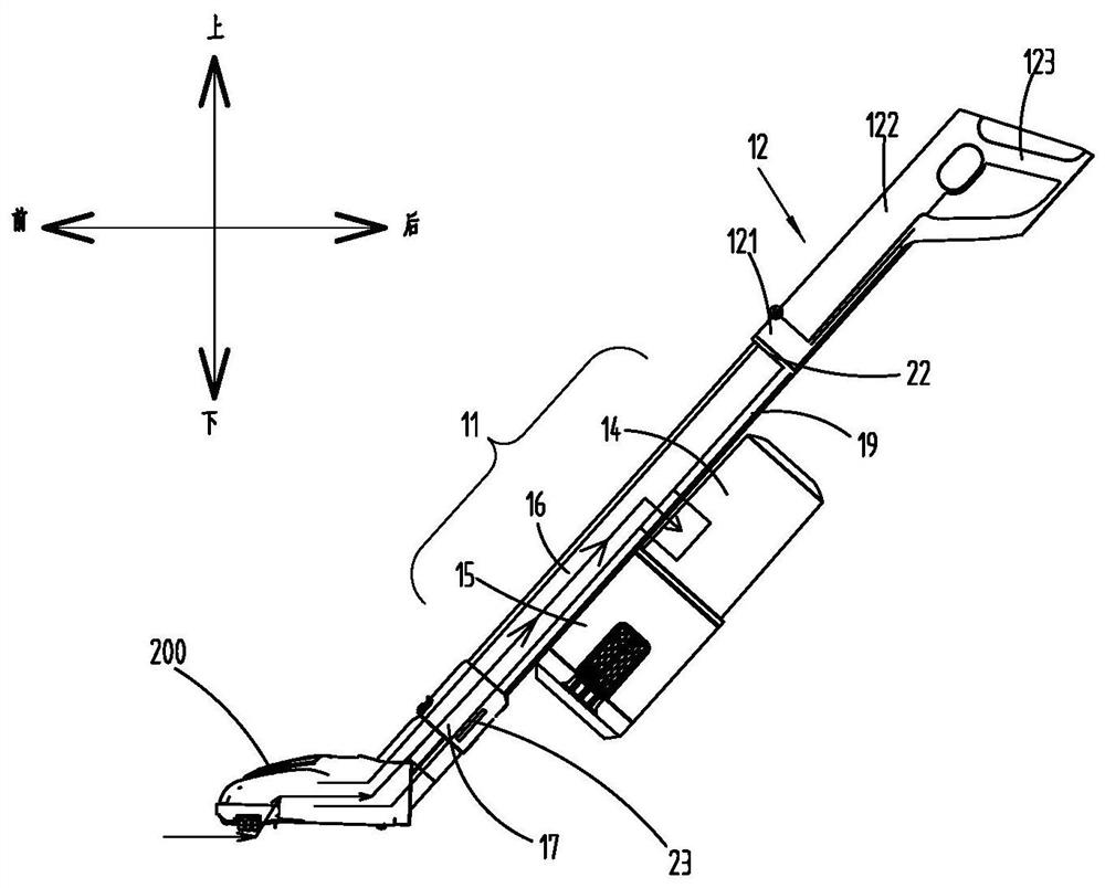
[0031] Such as figure 1 As shown, the vacuum cleaner includes a handheld vacuum cleaner body 100 and a cleaning head 200 connected to the vacuum cleaner body 100 . The lower part of the cleaning head 200 has a dirty air suction port, and the dust-laden airflow enters the vacuum cleaner main body 100 from the dirty air suction port.

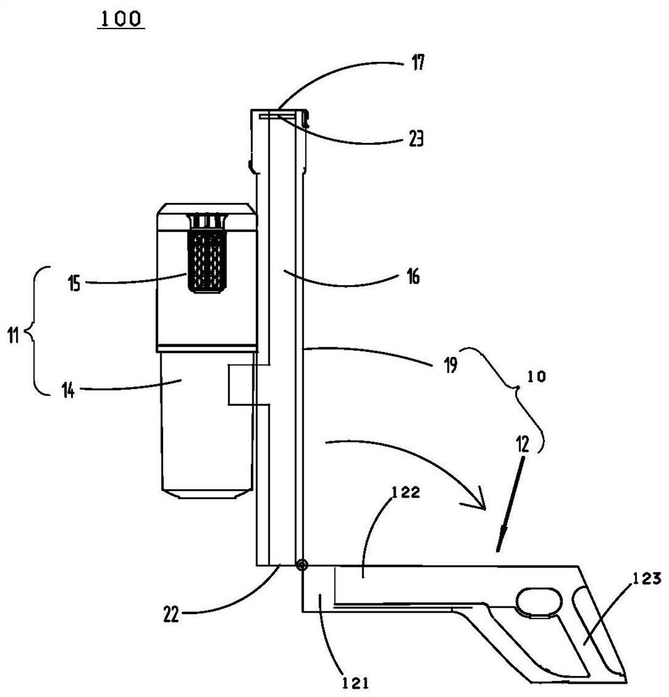
[0032] Such as figure 2 As shown, the vacuum cleaner main body 100 includes a deformable frame 10 and a portable surface cleaning unit 11 , and the deformable frame 10 can be deformed by unfolding and folding, so as to present different frame structures. The portable surface cleaning unit 11 includes a dust bucket 14, a vacuum motor 15, and a battery pack, etc., while the deformable frame 10 includes an air circulation duct 19 and a handle bar 12, and the air circulation duct 19 is hollow inside, forming a connection between the cleaning head 200 and the dust bucket. 14 part of the fluid path 16 . The dust bucket 14 and the dust suction motor ...

Embodiment 2

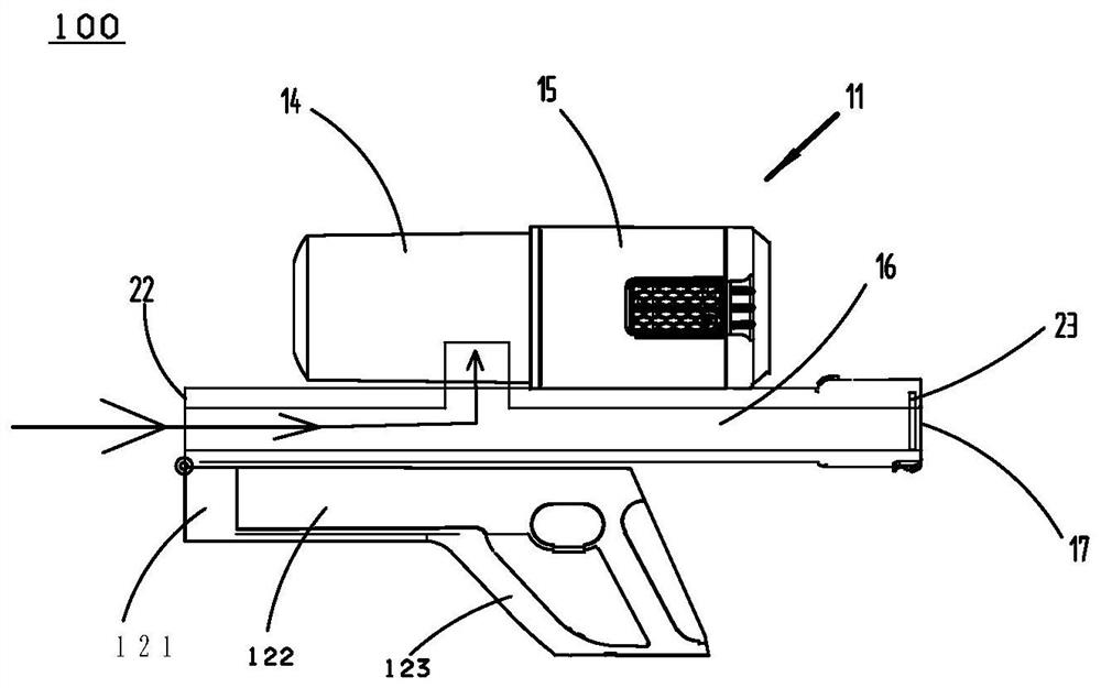
[0042] In order to simplify the description, the difference between Embodiment 2 and Embodiment 1 is that, compared with Embodiment 1, the connection between the air circulation conduit 19 and the handle bar 12 in Embodiment 2 is detachable, and the portable surface cleaning unit is always It is fixedly connected to the air circulation conduit, and in the first working mode and the second working mode, the same end of the air circulation conduit 19 is used for air intake.

[0043] Such as Figure 5 As shown, the vacuum cleaner main body 100 includes an air circulation conduit 19, and the dust bucket 14 and the dust collection motor 15 are fixed on the air circulation conduit. The front section of the air circulation duct is hollow, and the rear section is solid or closed by the second end 22 . The fluid path 16 passes through the hollow section of the air circulation duct and then extends into the dust bucket 14 through the air circulation duct. In the first working mode, the...


PUM


Abstract

The invention relates to a vacuum cleaner, comprising: a vacuum cleaner body and a cleaning head, the vacuum cleaner body includes a deformable frame and a portable surface cleaning unit, the portable surface cleaning unit includes a dust bucket and a dust collection motor, the deformable frame includes an air circulation duct and The handle bar, the portable surface cleaning unit is fixedly installed on the air circulation duct, the vacuum cleaner has two working states, in the first working state, the deformable frame is in the unfolded state, and the first end of the air circulation duct is connected with the cleaning head And the air flow is connected, the second end of the air circulation conduit is connected to the first part of the handle rod, the dust-laden air flow enters the dust bucket through the cleaning head and the air circulation conduit, and the center of gravity of the vacuum cleaner is located below the handle rod; in the second working state Next, the first end of the air circulation duct is separated from the cleaning head, the deformable frame is in a folded state, the first end of the air circulation duct is closed, the dust-containing airflow enters the dust bucket through the second end of the air circulation duct, and the vacuum The center of gravity of the vacuum cleaner is above the handle bar.

Description

technical field [0001] The invention belongs to the technical field of cleaning equipment, in particular to a vacuum cleaner. Background technique [0002] In the prior art, hand-held vacuum cleaners are favored by people because of their portability and flexibility. When users use hand-held vacuum cleaners to clean small areas, such as the bottom of sofas, the bottom of coffee tables, dead corners of walls, and the interior of cars, etc. For dust collection, users often attach cleaning accessories to the hand-held vacuum cleaner to complete the above-mentioned dust collection work, for example, attach a section of air circulation duct to the hand-held vacuum cleaner, and then install a cleaning head on the other end of the air circulation duct. Use a handheld vacuum cleaner to vacuum the indoor floor to be cleaned; you can also attach a short vacuum tube or flat suction nozzle to vacuum other places above the ground, such as cobwebs on the ceiling. [0003] In the above st...

Claims


Application Information

Patent Timeline
Patent Type & Authority Patents(China)
IPC IPC(8): A47L5/24A47L9/00A47L9/32
CPCA47L5/24A47L9/00A47L9/248A47L9/322
Inventor 卞庄
Owner SUZHOU CHENGHE CLEANING EQUIP
Why Eureka
Try Eureka