Mold taking manipulator for injection molding

A technology of manipulators and support seats, which is applied in the field of injection molding manipulators, can solve problems such as mold burns, easy clamping inaccuracies, and injection molding machine failures, and achieve the effect of accelerating cooling speed

Active Publication Date: 2021-06-11
苏州鑫叶自动化设备系统有限公司
View PDF7 Cites 1 Cited by
  • Summary
  • Abstract
  • Description
  • Claims
  • Application Information

AI Technical Summary

Problems solved by technology

[0006] Aiming at the deficiencies of the prior art, the present invention provides an injection mold taking manipulator, which solves the problem that the mold taking manipulator is very troublesome to take materials for some injection molded parts with high surface precision, and the traditional manual taking materials are easily scalded by high temperature molds. However, traditional manipulators generally use grippers. When retrieving materials, it is easy to clamp inaccurately and cause the workpiece to fall, causing the problem of injection molding machine failure.

Method used


Image

  • Mold taking manipulator for injection molding
  • Mold taking manipulator for injection molding
  • Mold taking manipulator for injection molding

Examples


Embodiment 1

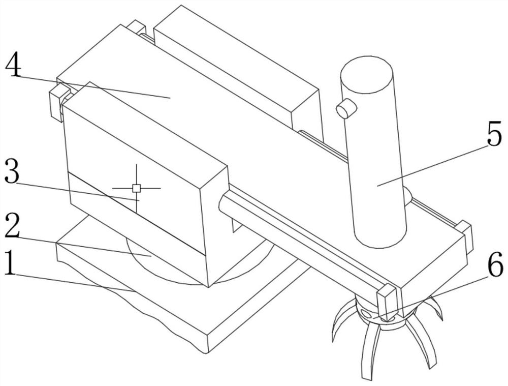
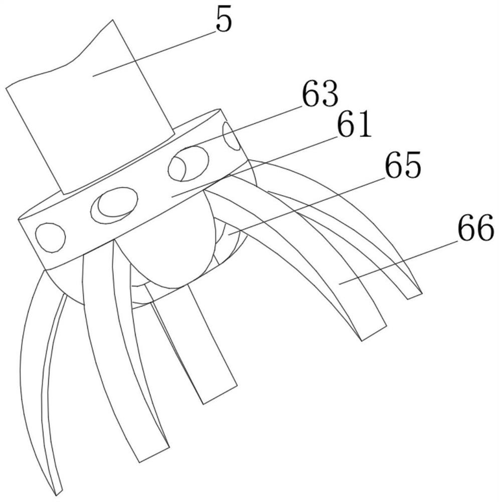
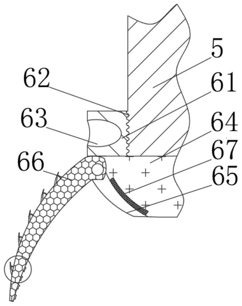
[0035] see Figure 1-4 , the present invention provides a technical solution: an injection mold taking manipulator, comprising a support base 1, the top of the support base 1 is rotatably connected to a rotation shaft 2, and the end of the rotation shaft 2 away from the support base 1 is fixedly connected to a fixed slider 3, The side of the inner wall of the fixed slider 3 is connected with a moving rod 4 through a motor, and the top of the end of the moving rod 4 away from the fixed slider 3 is provided with a pneumatic lifting device 5, and one end of the pneumatic lifting device 5 runs through the moving rod 4 and is threaded with a mold taking robot 6 The model taking manipulator 6 includes a connection block 61, the top of the connection block 61 is provided with a threaded hole 62, the side of the connection block 61 is provided with a lock groove 63, the bottom of the connection block 61 is fixedly connected with a manipulator 64, and the side of the manipulator 64 is p...

Embodiment 2

[0038] see Figure 3-6, the present invention provides a technical solution on the basis of Embodiment 1: an injection molding manipulator, the inner diameter gripping device 665 includes a moving support rod a1, one end of the moving support rod a1 is rotatably connected to the installation and fixing groove 663, and the moving support One side of the rod a1 is rotatably connected to an arc-shaped connecting rod a2 through a rotating seat, and the end of the arc-shaped connecting rod a2 away from the moving pole a1 is fixedly connected to a rotating plate a3, and both ends of the rotating plate a3 are fixedly connected to the first airbag a4 , the bottom of the rotating plate a3 is rotatably connected to the support rod a5 through the rotating seat, the end of the first air bag a4 and the support rod a5 away from the rotating plate a3 is fixedly connected to the fixed plate a6, and the end of the rotating plate a3 away from the arc-shaped connecting rod a2 is set There is an ...

Embodiment 3

[0041] see Figure 3-7 , the present invention provides a technical solution on the basis of Embodiment 1: an injection molding manipulator, the outer diameter gripping device 666 includes a placing plate b1, and one side of the placing plate b1 is respectively provided with a vent hole b2 and a chute b3, the side of the inner wall of the chute b3 is slidably connected with the fixed block b4, one end of the fixed block b4 is fixedly connected with the third airbag b5, and the end of the third airbag b5 away from the fixed block b4 is fixedly connected with the outer diameter clamping shell b6, the fixed block The material on the side of b4 away from the third airbag b5 is a material with elasticity and heat resistance;

[0042] When in use, when the size of the injection molded part is relatively small, the outer diameter clamping device 666 is moved to the outer wall of the injection molded part by clamping the mold taking manipulator, and the fixed block b4 is moved to the ...


PUM


Abstract

The invention discloses a mold taking manipulator for injection molding. The top of a supporting base is rotationally connected with a rotating shaft, the end, away from the supporting base, of the rotating shaft is fixedly connected with a fixed sliding block, the side face of the inner wall of the fixed sliding block is connected with a moving rod through a motor, and the top of the end, away from the fixed sliding block, of the moving rod is provided with a pneumatic lifting device. One end of the pneumatic lifting device penetrates through the moving rod and is in threaded with a mold taking manipulator body. A threaded hole is formed in the top of a connecting block, locking grooves are formed in the side faces of the connecting block, a mechanical arm is fixedly connected to the bottom of the connecting block, a connecting groove is formed in the side face of the mechanical arm, and a mold taking clamping jaw is rotationally connected to the side face of the inner wall of the connecting groove through a rotating pin. And an electromagnetic block is arranged at the bottom of the inner wall of the connecting groove. The invention relates to the field of injection molding equipment accessories. According to the mold taking manipulator for injection molding, injection molding parts with high surface precision can be conveniently taken out, and different mechanical arms do not need to be frequently replaced when the mold taking manipulator takes different injection molding parts.

Description

technical field [0001] The invention relates to the field of injection molding equipment accessories, in particular to an injection molding manipulator. Background technique [0002] Injection molding machine, also known as injection molding machine or injection machine, is the main molding equipment for making thermoplastics or thermosetting materials into various shapes of plastic products using plastic molding molds. Injection molding machines can be arranged according to the arrangement of injection devices and clamping devices. It is divided into vertical type, horizontal type and vertical-horizontal composite type. Injection molding machine is usually composed of injection system, mold clamping system, hydraulic transmission system, electrical control system, lubrication system, heating and cooling system, safety monitoring system and reclaiming manipulator. [0003] For example, Chinese patent CN103273630A discloses a pneumatic injection molding machine manipulator, w...

Claims


Application Information

Patent Timeline
Patent Type & Authority Applications(China)
IPC IPC(8): B29C45/42
CPCB29C45/4225
Inventor 不公告发明人
Owner 苏州鑫叶自动化设备系统有限公司
Why Eureka
Try Eureka