Power transformation cabinet dehumidification device

A technology for transformer cabinets and cabinets, applied in the field of transformer cabinets, which can solve the problems of poor dehumidification effect and low dehumidification efficiency, and achieve the effects of convenient use, improved dehumidification efficiency, and good dehumidification effect

Inactive Publication Date: 2021-06-18
常州峰林电气有限公司
View PDF0 Cites 0 Cited by
  • Summary
  • Abstract
  • Description
  • Claims
  • Application Information

AI Technical Summary

Problems solved by technology

[0004] The purpose of the present invention is to solve the shortcomings of low dehumidification efficiency and poor dehumidification effect in the prior art, and propose a dehumidification device for substation cabinets

Method used


Image

  • Power transformation cabinet dehumidification device
  • Power transformation cabinet dehumidification device
  • Power transformation cabinet dehumidification device

Examples


Embodiment 1

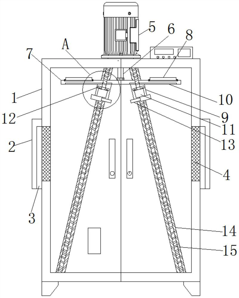
[0022] Embodiment 1. When the device is in use, the dehumidification device is installed on the cabinet 1 as a whole. When the humidity detector detects that the humidity inside the cabinet 1 reaches the set value, the humidity detector activates and transmits the signal to the controller, and then the The controller makes the push rod motor 5 and the heating tube 8 work at the same time to carry out dehumidification treatment. After the humidity drops, the humidity detector is activated again, and the listening motor 5 and the heating tube 8 are stopped by the controller, and the controller and the humidity detector are both It is an existing technology, and will not be described here. The controller adopts a PLC controller with a model number of S7-300.

Embodiment 2

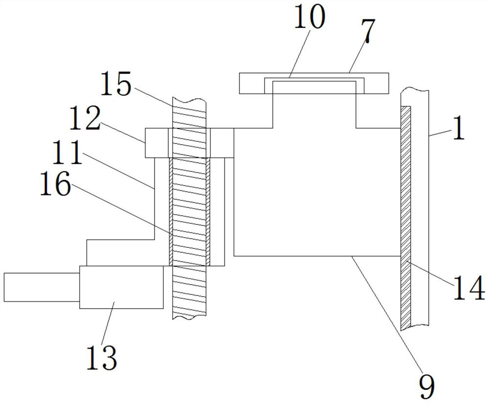
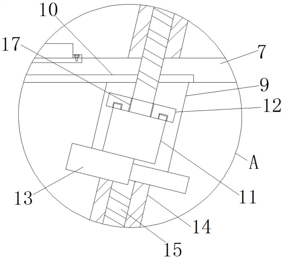
[0023] Embodiment two, after push rod motor 5 action, please refer to Figure 1-Figure 3 , the push rod motor 5 acts on the push rod 6 to push the push plate 7 to move downward, and the push plate 7 drives the heating tube 8 on the top to move up and down, so that the inside of the cabinet 1 is heated evenly, and at the same time, the push plate 7 drives the slider 9 at the bottom to move Sliding down, the slider 9 slides along the inclined chute 14, and when the slider 9 is displaced in the X-axis direction, it slides adaptively on the T-shaped slot 10;

[0024] Further, when the slider 9 drives the rotating mounting base 11 and the connecting plate 12 to move downward, the lead screw 4 passes through the through hole 17 of the connecting plate 12, the connecting plate 12 has no contact with the leading screw 15, and the rotating mounting base 11 When sliding downward, since the screw 15 is fixedly connected with the cabinet body 1, the screw 15 does not move, and the rotatin...


PUM


Abstract

The invention relates to the technical field of power transformation cabinets, in particular to a power transformation cabinet dehumidification device, and solves the defects of low dehumidification efficiency and poor dehumidification effect in the prior art, the power transformation cabinet dehumidification device comprises a cabinet body, the cabinet body is of a cavity structure, protective covers are fixed to the two sides of the cabinet body through bolts, moisture exhaust ports are formed in the protective covers, the top of the cabinet body is provided with a push rod motor through a bolt, the output end of the push rod motor is fixedly connected with a push rod, and through the arrangement of the push rod motor, a push plate, a sliding block, a sliding groove, a lead screw, an air heater, a rotating installation base and other structures, a device capable of automatically dehumidifying is additionally arranged in the cabinet body of the power transformation cabinet. In the operation process of the power transformation, the push rod motor enables the push plate to slide in a reciprocating mode, the sliding block drives the air heater to evenly dehumidify the interior of the cabinet body, the purpose of rapid dehumidification can be achieved in cooperation with the heating pipe, the dehumidification effect is good, and the dehumidification efficiency is greatly improved.

Description

technical field [0001] The invention relates to the technical field of transformer cabinets, in particular to a dehumidifier for a transformer cabinet. Background technique [0002] Today's power plants generally use variable voltage transmission, which converts the generated electric energy into high voltage for transmission with less loss. According to load requirements, power consumption is arranged, and the three-phase four-wire system is distributed in the transformer cabinet to achieve equipment use. Requirements, some electrical appliances need 380 volts, some need 220 volts, some equipment needs to be started directly, and some need inverters or soft starters, auto step-down starters, etc. The distribution of electrical cabinets is carried out in the transformer cabinet. [0003] The substation cabinets in the prior art are dehumidified by natural air drying or manual dehumidification. The dehumidification efficiency is not high, and the dehumidification effect is p...

Claims


Application Information

Patent Timeline
Patent Type & Authority Applications(China)
IPC IPC(8): B01D53/26B01D53/00
CPCB01D53/005B01D53/26
Inventor 眭银峰陆亚东
Owner 常州峰林电气有限公司
Why Eureka
Try Eureka