Machine cabinet intelligent dehumidifying controller and dehumidifying method

A control device and cabinet technology, which is applied in humidity control, non-electric variable control, control/regulation systems, etc., can solve the problems of high power, low dehumidification efficiency, and inability to continue to hold a large amount of moisture in dehumidifiers, so as to reduce power consumption, The effect of saving resources

Inactive Publication Date: 2016-01-27
杭州鸿程科技有限公司
View PDF5 Cites 0 Cited by
  • Summary
  • Abstract
  • Description
  • Claims
  • Application Information

AI Technical Summary

Problems solved by technology

However, part of the moisture contained in the air at a higher temperature stays in the air all the time. When the ambient temperature drops sharply, the air cannot continue to hold a large amount of moisture, and the precipitated air moisture will still condense on the electrical equipment.
Ordinary heating dehumidifiers generally have relatively large power and relatively low dehumidification efficiency ratio

Method used


Image

  • Machine cabinet intelligent dehumidifying controller and dehumidifying method
  • Machine cabinet intelligent dehumidifying controller and dehumidifying method
  • Machine cabinet intelligent dehumidifying controller and dehumidifying method

Examples


Embodiment 1

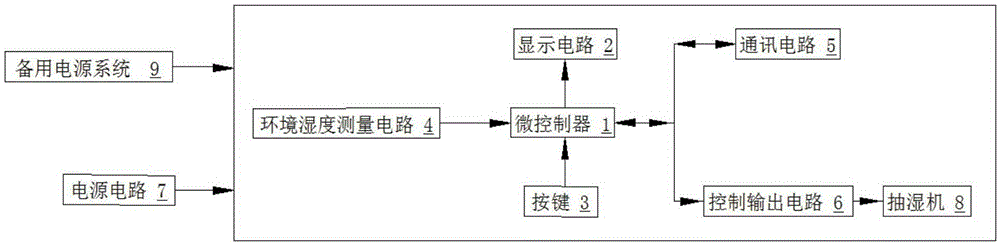
[0023] see figure 1 , an intelligent dehumidification control device for cabinets, comprising: a microcontroller 1, the main chip selected by the microcontroller 1 is: PIC16F1939, used for control, detection and output signals; the microcontroller 1 is connected to the environmental humidity measurement circuit 4, The control output circuit 6, wherein, the main chip selected by the environmental humidity measurement circuit 4 is: PS2701-1, which can measure the environmental humidity of 1-2 channels, and the device used in the control output circuit 6 is: G5LA-14-12VDC, which is used to control The dehumidifier dehumidifies the environment, and the control output circuit 6 is connected to 1-6 dehumidifiers 8. The dehumidifier uses a semiconductor dehumidifier, and uses a low-power TEC condenser as the main dehumidification component; the ambient humidity measurement circuit 4 measures For the humidity of the environment, the microcontroller 1 compares the measured ambient humi...

Embodiment 2

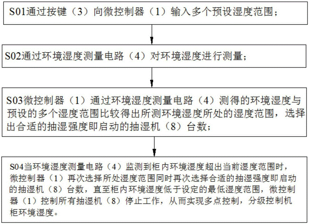
[0027] see image 3 , a dehumidification method suitable for a cabinet intelligent dehumidification control device, comprising the following steps: S01 inputs a plurality of preset humidity ranges to a microcontroller through buttons; S02 measures the ambient humidity through an ambient humidity measurement circuit; S03 a microcontroller The ambient humidity measured by the ambient humidity measurement circuit is compared with the preset multiple humidity ranges to obtain the humidity range of the measured ambient humidity, and the appropriate dehumidification intensity is selected, that is, the number of dehumidifiers to start; S04 when the ambient humidity When the measurement circuit detects that the ambient humidity in the cabinet exceeds the current humidity range, the microcontroller selects the humidity range again and at the same time selects the appropriate dehumidification intensity, that is, the number of dehumidifiers to start, until the ambient humidity in the cabi...


PUM


Abstract

The invention relates to a dehumidifying apparatus, and specifically relates to a machine cabinet intelligent dehumidifying controller and a dehumidifying method, wherein the machine cabinet intelligent dehumidifying controller comprises a micro-controller, wherein the micro-controller is connected to an environment humidity measuring circuit and a control output circuit; the control output circuit is connected to a plurality of dehumidifiers; the environment humidity measuring circuit is used to measure the humidity of the environment; and the micro-controller is used to control the plurality of the dehumidifiers through an output circuit based on the comparison between the measured environment humidity and a preset humidity range. According to the invention, multi-point humidity control can be realized; dehumidification is even; the gross power of all semiconductor dehumidifiers is not higher than 300W; and the number of the semiconductor dehumidifiers can be controlled at different levels, thereby controlling the environment humidity in the machine cabinet and greatly reducing the power use and saving resources; a standby power source system is provided, so even the machine cabinet is powered off, the power source system can provide an emergency power supply for 72 hours, thereby various circuits and elements in the machine cabinet can be normally operated.

Description

technical field [0001] The invention relates to a dehumidification device, in particular to an intelligent dehumidification control device and a dehumidification method for a cabinet. Background technique [0002] In order to improve the reliability of power supply and enable users to obtain power from two directions, the power supply network is usually connected into a ring. This power supply method is referred to as the ring network power supply. In industrial and mining enterprises, residential quarters, ports and high-rise buildings and other AC 10KV power distribution systems, due to the small load capacity, the high-voltage circuit is usually controlled by a load switch or a vacuum contactor, and is equipped with a high-voltage fuse for protection. The system is usually powered by a ring network, and the high-voltage switchgear used is generally called a ring network cabinet. [0003] When the ring main unit is out of service and the temperature of the equipment is l...

Claims


Application Information

Patent Timeline
Patent Type & Authority Applications(China)
IPC IPC(8): G05D22/02
Inventor 郭明皇
Owner 杭州鸿程科技有限公司
Why Eureka
Try Eureka