Display control method and device, electronic equipment and computer readable storage medium

A display control method and display area technology, applied in the field of display control methods, electronic equipment and computer-readable storage media, and display control method devices, capable of solving problems such as the influence of image visual effects and low brightness of displayed images in the sub-screen area, to achieve Good viewing effect, brightness continuity, the effect of brightness

Active Publication Date: 2021-07-02
BEIJING XIAOMI MOBILE SOFTWARE CO LTD
View PDF11 Cites 0 Cited by
  • Summary
  • Abstract
  • Description
  • Claims
  • Application Information

AI Technical Summary

Problems solved by technology

[0003] Since the density of pixels in the secondary screen area is lower than that of the main screen area, when images are displayed on the screen, the display effect of the secondary screen area will be different from that of the main screen area, which is mainly reflected in the relative brightness of the image displayed in the secondary screen area. is low, which affects the visual effect of the user watching the image

Method used


Image

  • Display control method and device, electronic equipment and computer readable storage medium
  • Display control method and device, electronic equipment and computer readable storage medium
  • Display control method and device, electronic equipment and computer readable storage medium

Examples


Embodiment Construction

[0079] Reference will now be made in detail to the exemplary embodiments, examples of which are illustrated in the accompanying drawings. When the following description refers to the accompanying drawings, the same numerals in different drawings refer to the same or similar elements unless otherwise indicated. The implementations described in the following exemplary examples do not represent all implementations consistent with the present disclosure. Rather, they are merely examples of apparatuses and methods consistent with aspects of the present disclosure as recited in the appended claims.

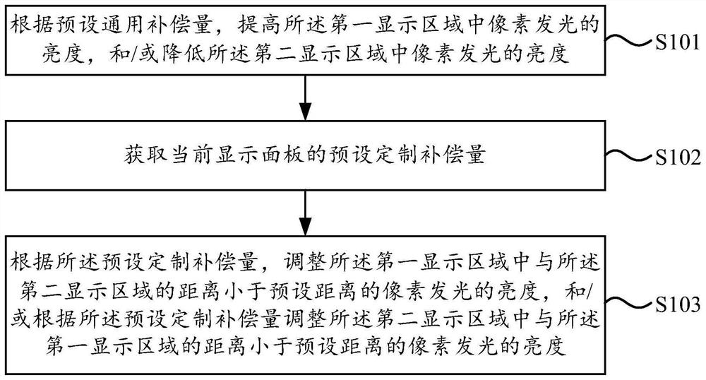
[0080] figure 1 It is a schematic flowchart of a display control method shown according to an embodiment of the present disclosure. The display control method may be applicable to a display panel, where the display panel may be an Organic Light-Emitting Diode (Organic Light-Emitting Diode, OLED for short) display panel.

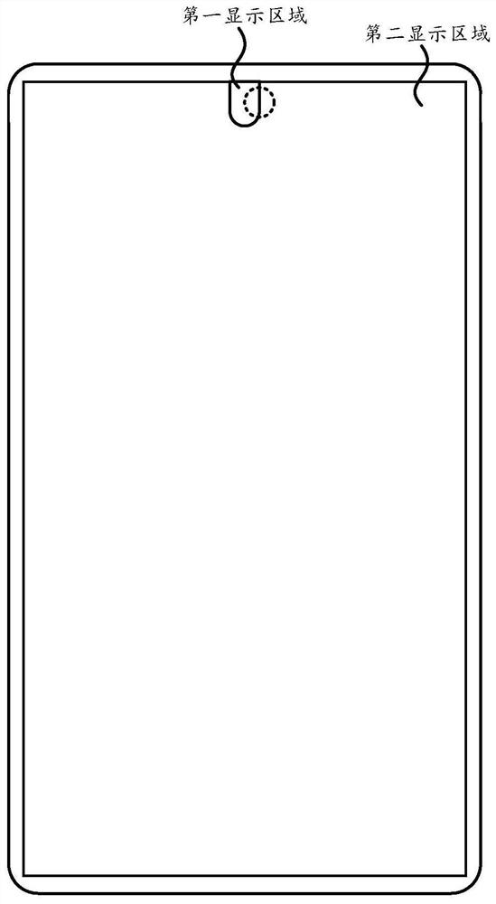
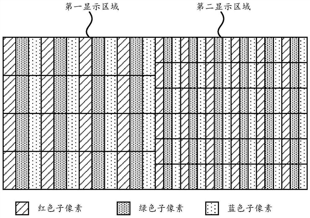
[0081] figure 2 is a schematic diagram of a display panel ac...


PUM


Abstract

The invention relates to a display control method and device, electronic equipment and a computer readable storage medium, and the method comprises the steps: according to a preset general compensation amount, increasing the brightness of pixel light emission in a first display area, and/or reducing the brightness of pixel light emission in a second display area; acquiring a preset customized compensation amount of the current display panel; and according to a preset customized compensation amount, adjusting the brightness of the light emitted by the pixels, the distance between which and the second display area is smaller than a preset distance, in the first display area, and/or according to the preset customized compensation amount, adjusting the brightness of the light emitted by the pixels, the distance between which and the first display area is smaller than the preset distance, in the second display area. According to the embodiment of the invention, the brightness difference of the junction of the first display area and the second display area can be accurately eliminated for each display panel, so that the brightness of the junction of the first display area and the second display area has continuity, an obvious boundary is not easy to be observed by a user, and a good viewing effect is ensured.

Description

technical field [0001] The present disclosure relates to the field of display technology, and in particular, to a display control method, a display control method device, electronic equipment, and a computer-readable storage medium. Background technique [0002] In order to increase the proportion of the screen in terminals such as mobile phones, a structure in which the front camera is placed under the screen is proposed in related technologies, and in order to enable the front camera to collect images through the screen, the density of pixels in the screen is designed. Specifically, a lower pixel density is set for the secondary screen area, a higher pixel density is set for the main screen area, and then the front camera is set under the secondary screen area. [0003] Since the density of pixels in the secondary screen area is lower than that of the main screen area, when images are displayed on the screen, the display effect of the secondary screen area will be differen...

Claims


Application Information

Patent Timeline
Patent Type & Authority Applications(China)
IPC IPC(8): G09G5/10
CPCG09G5/10G09G2320/0233G09G2320/0626
Inventor 刘伟光
Owner BEIJING XIAOMI MOBILE SOFTWARE CO LTD
Why Eureka
Try Eureka