Passive intelligent optical cable cross connecting cabinet management system

A management system and technology of optical delivery box, applied in the field of passive intelligent optical delivery box management system, can solve the problems of difficult active management, inability to guarantee battery life, difficult to popularize and apply on a large scale, etc.

Active Publication Date: 2021-07-06
GUANGZHOU MANHANG COMM TECH
View PDF11 Cites 0 Cited by
  • Summary
  • Abstract
  • Description
  • Claims
  • Application Information

AI Technical Summary

Problems solved by technology

[0002] At present, China Mobile, China Unicom, and telecom operators deploy a large number of optical cable passive optical transmission boxes outdoors, especially in first-tier cities. They can be seen everywhere. Optical cable transmission boxes are generally installed outdoors, which are dumb resources and passive equipment. Boxes The body and internal optical fiber accessories, long-term operation outdoors, complex and changeable and harsh environment, and human sabotage factors have potential threats to the safety of the optical cable transfer box
[0003] The distribution of optical cable transfer boxes is scattered and the number is huge, it is impossible to access the power supply, and it is difficult to realize active management. At present, there are some active optical transfer box monitoring equipment on the market: powered by solar energy, disposable batteries or rechargeable lithium batteries, The traditional electric sensing technology is used to realize the unlocking management and monitoring of the box, but the light box is exposed outdoors for a long time, the battery life cannot be guaranteed, and the maintenance cost of external solar energy is high, and the input cost is high, so it is difficult to promote and apply on a large scale

Method used


Image

  • Passive intelligent optical cable cross connecting cabinet management system
  • Passive intelligent optical cable cross connecting cabinet management system
  • Passive intelligent optical cable cross connecting cabinet management system

Examples


Embodiment Construction

[0028] This part will describe the specific embodiment of the present invention in detail, and the preferred embodiment of the present invention is shown in the accompanying drawings. Each technical feature and overall technical solution of the invention, but it should not be understood as a limitation on the protection scope of the present invention.

[0029] In the description of the present invention, multiple means more than two, greater than, less than, exceeding, etc. are understood as not including the original number, and above, below, within, etc. are understood as including the original number. If the description of the first and second is only for the purpose of distinguishing the technical features, it cannot be understood as indicating or implying the relative importance or implicitly indicating the number of the indicated technical features or implicitly indicating the order of the indicated technical features relation.

[0030] In the description of the present...


PUM


Abstract

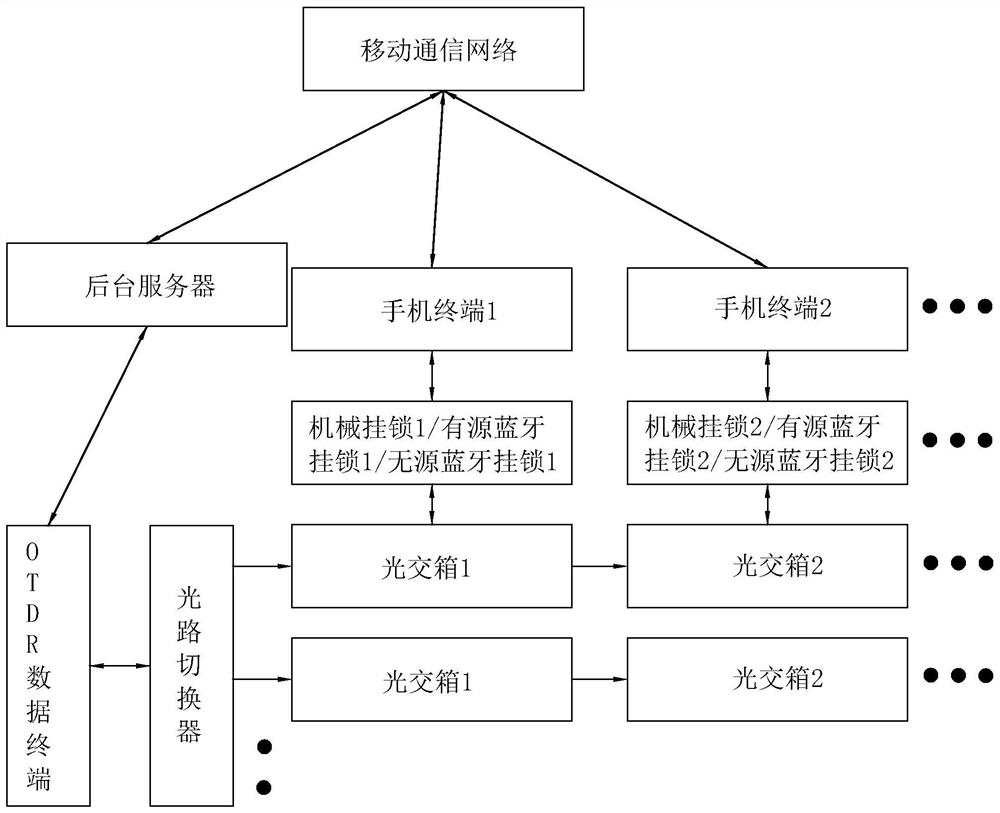
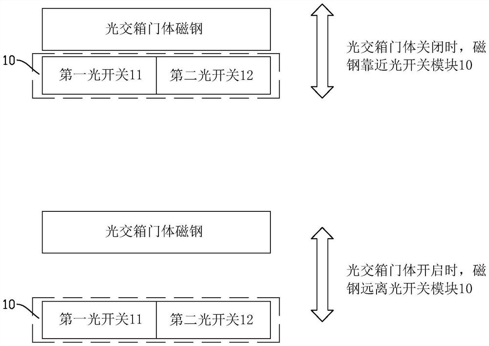
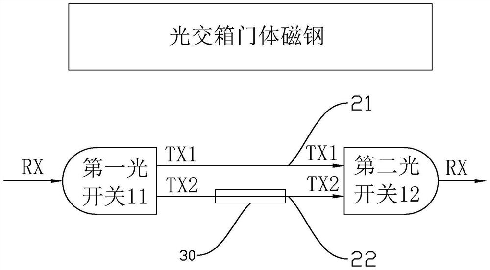
The invention discloses a passive intelligent optical cable cross connecting cabinet management system. The system comprises an OTDR data terminal and a plurality of cascaded optical switch modules, wherein the OTDR data terminal is connected with a background server; each optical switch module is arranged on one optical cable cross connecting cabinet magnetic door body, and each optical switch module comprises an input end, an output end, and a first optical line and a second optical line of which the two ends are connected with the input end and the output end respectively; the input end of one optical switch module is connected with the OTDR data terminal or the output end of the other optical switch module, the output end of one optical switch module is connected with the input end of the other optical switch module, an optical path attenuator is arranged on each second optical path, and the optical switch modules can be kept in the first optical lines when the optical cable cross connecting cabinet magnetic door bodies are closed or can be switched to the second optical lines when the optical cable cross connecting cabinet magnetic door bodies are opened; and opening and closing of a door lock correspond to different optical lines of the optical switch modules, the system detects light attenuation of the different optical lines to judge whether the magnetic door bodies are opened or not, and passive monitoring is achieved.

Description

technical field [0001] The invention relates to the field of optical fibers, in particular to a passive intelligent optical delivery box management system. Background technique [0002] At present, China Mobile, China Unicom, and telecom operators deploy a large number of optical cable passive optical transmission boxes outdoors, especially in first-tier cities. They can be seen everywhere. Optical cable transmission boxes are generally installed outdoors, which are dumb resources and passive equipment. Boxes The body and internal optical fiber accessories, long-term operation outdoors, complex and changeable and harsh environment, and human sabotage factors have potential threats to the safety of the optical cable transfer box. [0003] The distribution of optical cable transfer boxes is scattered and the number is huge, it is impossible to access the power supply, and it is difficult to realize active management. At present, there are some active optical transfer box monit...

Claims


Application Information

Patent Timeline
Patent Type & Authority Applications(China)
IPC IPC(8): E05C19/16G01D5/26H04B10/071
CPCE05C19/166H04B10/071G01D5/268
Inventor 陈玉清李耀枝吴监强
Owner GUANGZHOU MANHANG COMM TECH
Why Eureka
Try Eureka