
Acceleration sensor and sensing system based on variable-thickness air gap patch antenna

A technology of acceleration sensor and patch antenna, which is applied in speed/acceleration/shock measurement, acceleration measurement, acceleration measurement using inertial force, etc. It can solve the problems of difficult installation, expensive, and more space, and achieve the realization of accelerometer measurement , reduce the cost of measurement, and achieve the effect of large range

Pending Publication Date: 2022-07-29
TONGJI UNIV
View PDF5 Cites 0 Cited by
  • Summary
  • Abstract
  • Description
  • Claims
  • Application Information

AI Technical Summary

Problems solved by technology

However, on the one hand, these sensors are difficult to install and are relatively expensive, so they are difficult to apply to normalized and distributed acceleration sensing systems; The probability of failure during rotation is high, and it is difficult to apply to concrete embedded monitoring and acceleration monitoring of rotating bodies, which limits the development of active acceleration sensors

Method used


Image

  • Acceleration sensor and sensing system based on variable-thickness air gap patch antenna
  • Acceleration sensor and sensing system based on variable-thickness air gap patch antenna
  • Acceleration sensor and sensing system based on variable-thickness air gap patch antenna

Examples


Embodiment 1

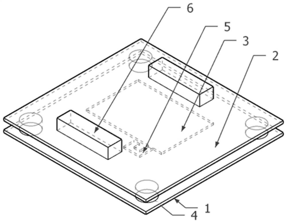
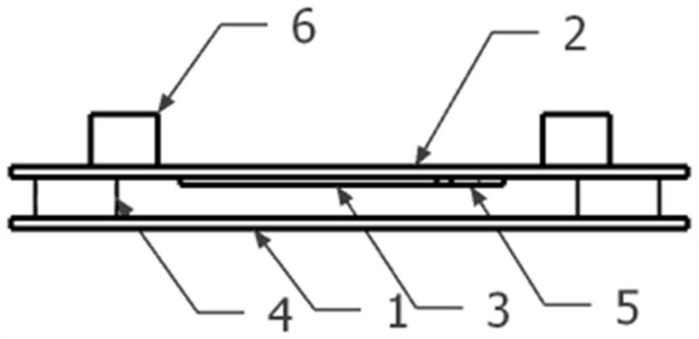
[0029] An acceleration sensor based on a variable thickness air gap patch antenna, such as figure 1 and figure 2 , including the ground plane 1, the support plate 2, the radiation patch 3, the elastic material 4, the chip 5 and the counterweight 6, the elastic material 4 is arranged between the ground plane 1 and the support plate 2, the radiation patch 3, the chip 5 and The counterweight 6 is arranged on the support plate 2 , and the chip 5 is electrically connected to the radiation patch 3 .

[0030] Coded information is stored in the chip 5 .

[0031] The installation process of the accelerometer is as follows:

[0032] First, the elastic material 4 is glued under the ground plane 1;

[0033] Next, the radiation patch 3 is plated under the support plate 2 by an immersion gold process.

[0034] Next, the chip 5 is welded on the pallet 2;

[0035] Next, the counterweight 6 is glued on the pallet 2;

[0036] Finally, the pallet 2 is glued above the elastic material 4, p...

Embodiment 2

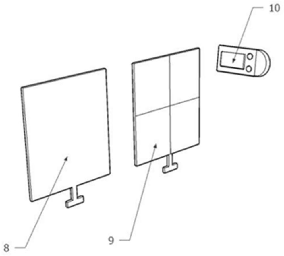
[0043] A sensing system such as figure 1 , figure 2 and image 3 , including a detection module and an acceleration sensor 7, the detection module includes a data acquisition device 8, a reader 10 and a transmitting antenna 9 that are electrically connected in sequence, and the acceleration sensor 7 is the variable thickness air gap patch antenna described in Embodiment 1. Accelerometer;

[0044] like image 3 When the system is working, the acceleration sensor 7 is placed on the surface of the structure to be measured 11, the reader 10 transmits electromagnetic wave signals through the transmitting antenna 9, activates the sensor chip 5, and detects the resonance of the radiation patch 3 along the direction perpendicular to the pallet 2 respectively. The frequency changes and is uploaded to the data acquisition device 8 , and the data acquisition device 8 calculates the real-time displacement of the sensor, and then obtains the acceleration information of the structure to...


PUM


Abstract

The invention relates to an acceleration sensor based on a variable-thickness air gap patch antenna, which comprises a grounding plane (1), a supporting plate (2), a radiation patch (3), an elastic material (4), a chip (5) and a balancing weight (6), the elastic material (4) is arranged between the grounding plane (1) and the supporting plate (2), the radiation patch (3), the chip (5) and the balancing weight (6) are arranged on the supporting plate (2), and the chip (5) is electrically connected with the radiation patch (3). Compared with the prior art, passive monitoring is realized, the layout cost is low, the layout difficulty is small, and wide-range accelerometer measurement can be realized.

Description

technical field [0001] The invention relates to the field of structural health monitoring, in particular to an acceleration sensor based on a variable thickness air gap patch antenna. Background technique [0002] Acceleration information is currently widely used in the calibration of structural wind resistance and earthquake resistance, aircraft safety performance evaluation, car accident alarm, high-voltage wire galloping and other scenarios. Acceleration sensors are generally required to collect acceleration information. Traditional acceleration sensors, including vibrating wire sensors, capacitive sensors, optical fiber sensors, etc., can detect dynamic acceleration of structures. However, because traditional sensors use cables for data transmission and energy supply, in complex detection environments, It often produces extremely complex wiring, requires high labor costs, and is difficult to troubleshoot and repair after detecting system failures. The acceleration sens...

Claims


Application Information

Patent Timeline
Patent Type & Authority Applications(China)
IPC IPC(8): G01P15/097G01P15/08
CPCG01P15/097G01P15/0802
Inventor 谢丽宇吴通海
Owner TONGJI UNIV
Learn More